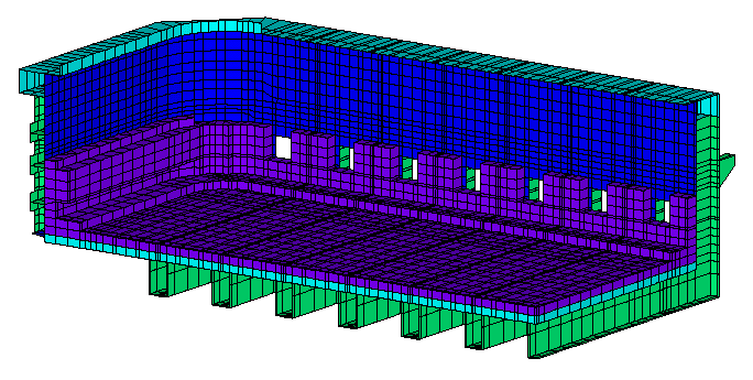
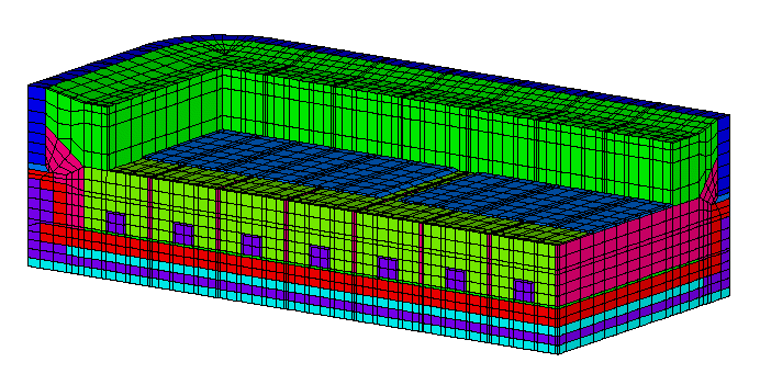
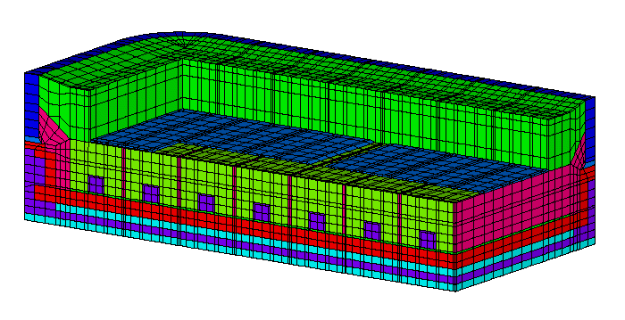
Figure 1: Model mesh: potshell and insulating brick layer
THERMAL STUDY OF THE COKE PREHEATING FOR
HALL-HEROULT CELL
Marc Dupuis, Ghasem Asadi and C. Mark Read
Alcan International Limited, Arvida Research and Development Centre
Jonquière, Quebec, Canada G7S 4K8
Raymond Thellend and Steve A. Tomlinson
Société d'électrolyse et de chimie Alcan Ltée
Jonquière, Québec, Canada G7S 4L2
Imad Tabsh
Compusim Inc.
1003-D 55th Avenue N.E. Calgary, Alberta, Canada T2E 6W1
ABSTRACT
The impact of some parameters of the Hall-Héroult cell coke preheating technique upon the cathode block temperature is assessed. The assessment is based upon a three-dimensional transient thermal-electrical ANSYS® finite element model which has been validated using measurements taken during the preheating of 150 kA cells. The influence of parameters, such as the power curve and coke bed geometry upon cathode block temperature is discussed. Various recommendations are made to reduce the magnitude of thermal gradients within the cathode blocks thus reducing crack susceptibility.
INTRODUCTION
The average life of the cathode lining of a Hall-Héroult cell varies typically from 1500 to 3500 days. For a particular aluminum reduction cell technology, the average life is determined by different design parameters such as shell strength, cathode design, collector bar configuration etc. It was also observed that a cathode failure could happen due to undesirable thermal stress generated during the cell preheat phase [1].
A sound preheat practice is an important factor which has a major effect on the cathode lining life. It insures that thermal gradients generated in the cathode lining are minimized. In the case of the coke preheat technique, a uniform coke bed layer combined with the usage of individual anode flexible insure a uniform anodic current distribution which, combined with a shunting technique, insure a low and uniform heating rate necessary to minimize thermal gradient buildup. If, despite all the above precaution, the early failure rate remains too high regardless of the quality of carbon blocks used, a more detailed analysis is required to identify problems that could have been overlooked.
To further reduce the early failure rate, a better understanding of the transient behaviour of the cathode lining during the cell preheat was required. The present work is an investigation to find the magnitude and distribution of the transient thermal gradients occurring in the cathode lining during the preheat phase. With this aim, the numerical analysis methods with modern computer facilities, hardware and software, have been selected. More precisely a finite element model based on the commercially available finite element code ANSYS has been developed and run on a Silicon Graphics workstation.
Description of the Model
The complex geometry and generation of heat within the anode, coke bed and cathode makes a combined calculation of the heat and current flow by finite element methods desirable.

Figure 1: Model mesh: potshell and insulating brick layer
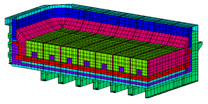
Figure 2: Model mesh: refractory brick, side carbon, mix and cathode carbon block
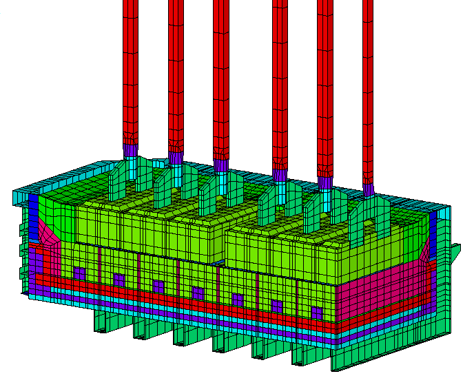
Figure 3: Model mesh: + coke layer, cryolite and anodes in standard configuration
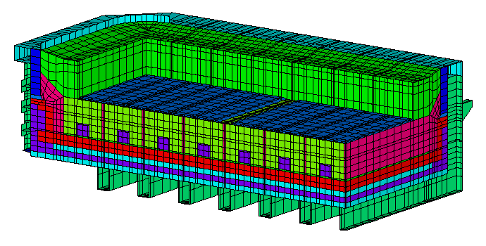
A finite element of the cell to be investigated was developed using ANSYS. The model mesh included the potshell and insulating brick layer (Figure 1), refractory brick, side carbon, mix and cathode carbon block (Figure 2), coke bed, cryolite and anodes (Figure 3) for a full quarter of the cell to be studied.
The model was designed to meet several requirements including:
| · | Study different coke bed configurations namely: the uniform, strip and ring coke bed (Figure 4). |
a) Uniform coke bed
b) Strip coke bed
c) Ring coke bed
| · | Study different anode configurations namely the standard and moved first anode configuration (Figure 5). |
| · | Study different shunting schedules. This requirement involves the readjustment of the amperage at given time intervals (Figure 6). This requirement also involves that the model should follow the measured pot voltage at every amperage level. This was achieved by continuous adjustment of the coke resistivity using an ANSYS APDL macro. |


| · | Perform a transient coupled field thermoelectric analysis. The Joule heat resulting from the electric current following in the cell being the only source of heat input. Heat is accumulated in the lining so the density and specific heat of each material must be provided in addition to the thermal conductivity and electrical resistivity required for steady-state analysis. Heat is lost on the outside surface of the potshell and anodes through convection and radiation. |
| · | Represent non-linear behaviour. Material properties are a cubic function of temperature; convective
surface film coefficients are also temperature dependent; and radiation effects have a fourth order variation with temperature. All these non-linearities were accounted for in the model. |
| · | Variable model size. Three levels of problem complexity were allowed for in the input scheme: a center section model representing the section of the cell from centerline up to the tapping channel; a corner model representing the cell corner up to the tapping channel (Figure 7) and the full quarter of the cell. The last model obviously requires more computing resources. Using smaller models provides a quicker method of evaluating changes. |

Validation of the Model
As with any mathematical model, a validation exercise must be performed prior to declaring the model "fit for duty". Isotherms at a given time like those presented in Figure 8 after 36 hours of preheat represent the typical model results. But for the purpose of validation, a time history graph of the temperature evaluation at one point in the lining is more appropriate.


To obtain experimental data, an extensive instrumentation package was developed and used on many cells. On Figure 9 results of 3 ANSYS runs with slightly different model setups are compared with results from 8 experimental curves obtained from 4 different preheats. After some adjustment of the materials properties, the boundaries conditions and the power curve, the model was considered reliable to perform case study analysis.
Effect of the Coke Bed and Anode Configuration on the Thermal Gradient in the Cathode Blocks
Results of three cases run using the corner mesh version of the model are presented here. In the first run, the uniform coke bed and the standard anode position was selected. The isotherms in the carbon blocks at the end of the 36 hours preheat are presented in Figure 10. We can easily observe the high thermal gradient present in the first cathode block (the first one from the left in Figure 10).


In the second run, the strip coke layer and the standard anode position were selected (see isotherms in Figure 11). The effect of the strip coke bed was to reduce the area with high thermal gradient in the first block but in doing so, new thermal gradients have been generated in the centerline region of the cathode panel.
In the third run, the uniform coke bed and the moved first anode position was selected (see isotherms in Figure 12). The effect of moving the first anode towards the end wall to cover more of the first cathode block was to reduce the thermal gradient in this block. Only a stress analysis will be able to assess if that change is enough to eliminate the risk of block cracking.

CONCLUSION
The finite element method provides and excellent tool for the study of transient thermal gradients that develop during coke preheat. The effect of different preheat set-ups have been analysed successfully using the model.
In the second phase of development of the model the stress analysis will be performed. In that stress analysis, both the thermal stress from the thermal gradient in the blocks themselves and the mechanical stress from the potshell structure restraint will be considered in a full 3-D analysis.
REFERENCES