MODELING POWER MODULATION

Marc Dupuis
GéniSim
3111 Alger St.
Jonquière, Québec, Canada G7S 2M9
http://www.genisim.com
e-mail:

Abstract

With the recent power shortage in the USA, aluminum smelters are getting strong incentive to reduce their power consumption during peak demand. This power modulation can be quite harmful to the cells if not done properly. Yet, some smelters in Brazil [1,2] are now successfully managing power modulation on a routinely basis following a long and expensive learning curve.

Nowadays however, efficient dynamic cell simulator can be used in order to accelerate this learning curve and reduce the risk involved in performing power modulation without enough background experience. In this paper, two dynamic models are applied to study power modulation: an ANSYS based 2D+ full cell slice thermo-electric model and a much faster "lump parameter+" model.

Introduction

In the context of an electrical power shortage in the USA, aluminum smelters, the most intensive electrical power consumers [3], are more and more forced to include a "power modulation" clause when renewing their long-term power supply contracts.

As described previously [4], the terms of those power modulation clauses are generally profitable to both the smelter and the power company, assuming that this practice does not have a significant negative impact on the smelter operations.

This challenge has been successfully met by some smelters [1,2,4]. They had to address, among other problems, an initial increase of the anode effect frequency by a factor 3 to 5 when the current was raised back to normal at the end of a power curtailment.

Those smelters learned by trials and errors how to proceed in order to minimize the negative impact of performing power modulation on the process. Fortunately, nowadays, mathematical models can be used in order to avoid learning how to perform power modulation on a 1 billion dollars smelter!

Description of the mathematical models

When developing a mathematical model, two opposite requirements must be addressed:

· The model must accurately represent the key behaviors of the process to be modeled. In this case, the model must be able to accurately reproduce/predict the cell thermal response of a power modulation event.
· The model must be limited to a manageable size/complexity in order to keep both its development and computation time affordable.

Addressing both those opposite requirements at the same time is a real challenge, best addressed by experienced modelers. Failing to do so will produce either:

· A misleading "quick and dirty" model which usage could be worse than not using any models at all.
· A "monstrous" unmanageable model that could not possibly be used in the time frame of a smelter technical assistance project.

In that context, two numerical models have been developed.

The first one is an ANSYS based 2D+ full cell slice dynamic thermo-electric model [5]. This model was developed following a "top down" approach. This means that it was obtained by simplifying a more complex 3D full cell slice steady state thermo-electric model that has been extensively validated and used to assist many cell lining design projects [6,7]. This model is considered complete enough to well represent the dynamic behavior of the process under most circumstances.

Unfortunately, despite its simplification from a 3D to a 2D+ geometry and the constant increase of computer power, the sole usage of this model could drag down significantly a smelter technical assistance project by its long response time or prevent the full analysis of all the alternative options at the early phase of the project.


For that reason, a second model was developed following a "bottom up" approach, meaning that this time, the prime objective was to obtain fast answers. This model is based on the so-called "lump parameter" model concept [8,9].

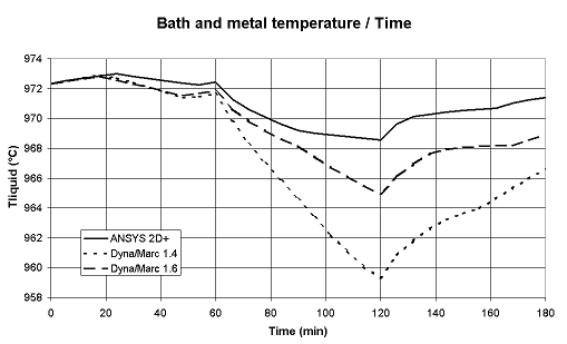
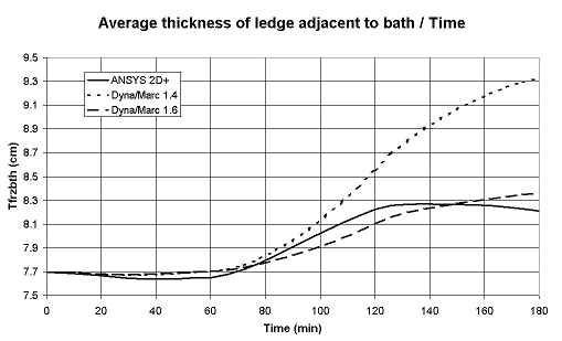
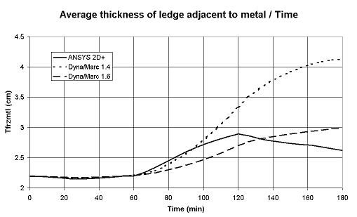
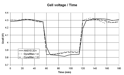
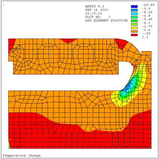
The original "lump parameter" model, as argued previously in [5] and illustrated in Figure 1, is accurate enough to be used to do fast analysis of the thermal response of a cell under normal operating conditions. But, as argued in [5] and illustrated in Figure 2, that model concept is not accurate enough to well represent the thermal response of a cell going through drastic exceptional events like a total power loss.

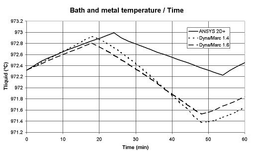
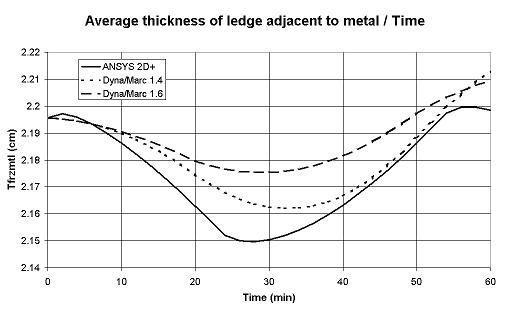
Figure 1: Normal operation

For that reason, the original "lump parameter" model had to be expanded to take into account the thermal response of the cell lining. That way, the model could be considered accurate enough to analyze the thermal response of power modulation events.

So an improved model has been developed and will be called a "lump parameter+" model. By definition, a "lump parameter" model is a 0D model. This means that no partial differential equations are used to solve thermal gradients like a 2D model does in 2 dimensions space or a 3D model does in 3 dimensions space.

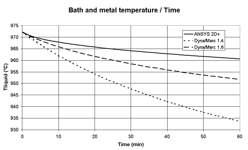
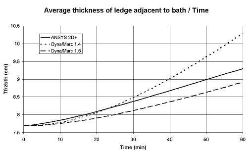
Figure 2: Total power failure

As the "+" in the 2D+ model stands for some crude representation of the third dimension in a 2D model [10], the "+" in the "lump parameter+" model stands for the addition of a 1D representation of the thermal diffusion in the anode and cathode panels as well as for the addition of a 1D representation of the thermal diffusion in the variable ledge thickness at bath and metal level [11].

This means that the "lump parameters+" model not only computes the thermal evolution of the lump mass of bath, metal and sludge, but also calculates the thermal gradients evolution in the anodes, the cathode blocks and the side ledge [12]. As seen in Figure 2, that improved model (denoted version 1.6) now reproduces fairly well the thermal response of a total power failure.

Still, the "lump parameter+" model computed the one hour thermal response in a fraction of second while the 2D+ model took 25 minutes wall clock time to compute it while running on a Pentium III, 800 MHz computer. Obviously, having access to both models is a tremendous advantage because, at the concept-screening phase of a project, speed is more important than accuracy while towards the end, accuracy becomes critical for fine-tuning the selected concept.


Modeling the thermal response of power modulation

In order to test both models on a power modulation case, the following scenario was analyzed:

· The cell was run at its nominal 300 kA amperage for one hour.
· The cell amperage was then suddenly dropped to 250 kA and kept at that reduced amperage for one hour without changing the anode cathode distance (ACD).
· Finally, the amperage was then suddenly increased back to 300 kA and the simulation was carried out for one additional hour.

As we can see in Figure 3, the predictions of both models are quite similar, but they are not identical:

· The 2D+ model predicts a drop of 4 ºC at the end of the current curtailment period while the "lump parameter+" model predicts a drop of 7 ºC.
· The 2D+ model predicts an increase of 8% of the ledge thickness at bath level while the "lump parameter+" model predicts an increase of 9%.
· The 2D+ model predicts an increase of 27% of the ledge thickness at metal level while the "lump parameter+" model predicts an increase of 36%.
· Both models predict the same type of slow recovery at the end of the current curtailment which if far from over at the end the one hour recovery. However, the 2D+ model does predict a somewhat faster recovery.

Again in this case, the single most important difference between the models is not find in the model's predictions themselves but in the time required to obtain them. The "lump parameter+" model can compute a 12 or even a 24 hours thermal response in a few seconds while the 2D+ model required 66 minutes of wall clock time to compute a 3 hours thermal response on a Pentium III, 800 MHz computer.

Obviously, the 2D+ model provides, on top of a more accurate global response, many more detailed results like the detailed evolution of the ledge profile including the evolution of the ledge toe and even the dissipation in the cell lining of the thermal wave generated by the power modulation (see Figure 4). That extra accuracy and information may be important depending on the context of the analysis performed.


Figure 3: Total power failure


Figure 4: Power modulation 2D+ model: temperature change after 3 hours

Performing power modulation without affecting the cell heat balance

In the previous case, the amperage of a cell was curtailed from 300 to 250 kA while the ACD was kept constant. This resulted in a decrease of the cell voltage to only 3.85 V corresponding to a power modulation of 22% (from 1230 to 960 kW).

This 22% power saving may well be the critical figure as far as the power supplier is concerned, but in terms of cell thermal response, the change of 32% (from 620 to 420 kW) of the cell internal heat is far more important.

This notable drop in the cell internal heat produces a quite significant thermal response as described previously. This needs not to be the case!

It is important to realize that a cell operating around 13 kWh/kg uses about half of this input electrical power to produce aluminum and the other half to maintain its thermal balance.

It is quite possible to develop a power modulation scenario where all the curtail power is removed from the half that produces the metal, leaving the cell internal heat unaffected.

One simply needs to remember that the equivalent power to make metal is directly proportional to the cell amperage, while the cell internal heat is directly proportional to the square of the cell amperage. So, a simple drop of the cell amperage will affect more the cell internal heat (the power required to maintain the cell heat balance) than the equivalent power to make metal.

Fortunately, the cell internal heat is also proportional to the ACD. This means that it is possible up to a point, to compensate the impact of the decrease of the current density in the bath on the internal heat by an increase of the cell ACD.

This scenario was analyzed with the "lump parameter+" model. The amperage was as previously dropped from 300 to 250 kA but this time after 3 hours of normal operation and for a period of 6 hours. But, this time, the cell target resistance was at the same time raised from 8.8 to 10.65 micro-ohm. This corresponds to an increase of 44% of the ACD (from 5.0 to 7.2 cm). As a result, the cell electrical power was only decreased by 16% (from 1230 to 1035 kW), but the cell operating temperature was not at all affected by the power modulation as seen in Figure 5 and 6.

Figure 5: Power modulation with ACD compensation


Figure 6: Power modulation with ACD compensation

It is important to point out that, in this "lump parameter+" model simulation, the cell temperature remained unaffected despite a still significant drop in the cell internal heat because the increase of the cell ACD did obviously also affect the bath level significantly (from 20 to 12 cm). As in the "lump parameter+" model, the heat dissipation through the ledge and side wall opposite to bath is proportional to the bath level, the "lump parameter+" model also predicted a decrease of the cell heat dissipation during that time.

For that reason, the "lump parameter+" model predicts that the thermal balance of the cell will be maintained by increasing that ACD to "only" 7.2 cm. It may turn out that a bit more ACD is required to maintain the thermal balance. Of course, the next step should be to analyze this power modulation scenario using the 2D+ model, but by lack of time, that analysis was not performed.

Conclusions

The previously presented dynamic "lump parameter" model [8,9] was successfully improved by adding 1D representation of the thermal diffusion in the anode and cathode panels as well as adding a 1D representation of the thermal diffusion in the variable ledge thickness at bath and metal level [11]. That improved "lump parameter+" model can far more accurately represent the thermal response of drastic events like a total power failure without any user perceptible increase on the CPU time required to compute it.

Both the 2D+ and the "lump parameter+" dynamic models were successfully used to compute the thermal response of a power modulation event. Although the predictions of both models are not identical, they are quite similar. The 2D+ model produces the most accurate results but required hours instead of seconds to compute them.

The "lump parameter+" model was used to demonstrate that it is possible to curtail down the input electrical power of a 300 kA cell up to 16% for a relatively long period of time without affecting significantly its thermal balance.


References

  1. A.C. Brant and al, "The Operation of a Smelter with Power Modulation", Light Metals, (1992), 357-362.

  2. L.J. Leal Nunes and al, "Power Modulation on Valesul P-19 Pots", Light Metals, (1998), 1267-1271.

  3. Aluminum Technology roadmap Workshop (Washington, D.C.: Aluminum assoc., 1997).

  4. N.E. Richards and H.O. Forberg, "Electrical Power Contracts and Other Factors Affecting Smelter Economics", Light Metals, (1997), 253-258.

  5. M. Dupuis and R. Lacroix, "Development of a 2D+ Dynamic Model of an Aluminum Reduction Cell", Proceeding of the 38th Conference on Light Metal, CIM, (1999), 41-55.

  6. M. Dupuis and I. Tabsh, "Thermo-Electric Analysis of Aluminum Reduction Cells", CIM Light Metals, (1992), 55-62.

  7. M. Dupuis and C. Fradet, "Using ANSYS® Based Aluminum Reduction Cell Energy Balance Models to Assist Efforts to Increase Lauralco's Smelter productivity", Proceeding of the ANSYS® 8th International Conference, volume 2, 2.233-2.240, (1998).

  8. I. Tabsh, M. Dupuis and A. Gomes, "Process Simulation of Aluminum Reduction Cells", Light Metals, (1996), 451-457.

  9. M. Dupuis, "Process Simulation", TMS Course on Industrial Aluminum Electrolysis, (1997).

  10. M. Dupuis, "Computation of Aluminum reduction Cell Energy Balance Using ANSYS® Finite Element Models", Light Metals, (1998), 409-417.

  11. C.C. Wei and al, "Modelling of Dynamic Ledge Heat Transfer", Light Metals, (1997), 309-316.

  12. 12. M. Dupuis and H. Côté, DYNA/MARC version 1.6 User's Guide, (2001).