THERMO-ELECTRIC ANALYSIS OF THE GRANDE-BAIE ALUMINUM REDUCTION CELL


Marc Dupuis
Alcan International Limited
Arvida Research and Development Centre
1955 Mellon Blvd.
Jonquière, Québec, Canada G7S 4K8

ABSTRACT

The cathode of an aluminum reduction cell consists of a steel structure lined with bricks and other insulation materials. An efficient cell cathode design has an optimum heat balance that minimizes energy consumption and cell failure. The design relies on the solidification of the electrolyte against the side of the cathode to provide a "freeze" layer which protects the lining against erosion.

A three dimensional thermo-electric finite element ANSYS® model of a full quarter of the cathode was defined parametrically to allow for quick evaluation of design changes. For a given cathode design and cell amperage, the model calculates the steady state heat balance and freeze profile. For validation purposes, model results are compared against thermo-electric measurement campaigns (blitz).

INTRODUCTION

One of the mandates of the Electrolysis Technical Group is to develop analytical tools necessary to support major aluminium smelters. Advanced mathematical models are viewed as useful tools to help meet the environmental, technical and economic challenges that lie ahead.

This paper describes the use of the commercially available finite element program ANSYS to model the thermo-electric behavior of the aluminum reduction cells used at the Grande-Baie smelter.

Optimum Thermo-Electric Cell Design

Considerable electrical energy, around 14.5 kilowatt-hour per kilogram of aluminum for the Grande-Baie cell technology, is expended during the aluminum reduction process. Maintaining the proper heat balance in the cell is critical for minimizing energy consumption and promoting ease of cell operation. The design of the cell should be such that it maintains the correct operating temperature without excessive freeze coverage of the cathode blocks leading among other things to higher cell voltage, but with sufficient freeze to cover the side wall to prevent excessive side wall erosion and early side-lining failure.

Hence, thermo-electric optimization has the benefit of reducing both operating costs as well as the environmental impact of the process.


Imad Tabsh
Compusim Inc.
1003 D 55th Avenue N.E.
Calgary, Alberta, Canada T2E 6W1

FINITE ELEMENT MODELING

The complex geometry and generation of heat within the cathode lining makes a combined calculation of the heat and current flow by finite element methods desirable. A thermo-electric model allows for the calculation of the location of isotherms in the lining, the freeze profile and the heat dissipated by the cathode. After validation of the model results against measurements obtained from thermo-electric "blitz" campaigns, the model can be used to investigate changes in the lining materials as well as changes in the process parameters.

Quarter Model Description

The cell technology used at the Grande-Baie smelter, with its sloped potshell side wall, its curved potshell end wall and its intricate pier design, has one of the more complex cathode lining geometries in the aluminum industry (Figure 1). The representation of such a complex geometry by a parametric finite element model proved to be quite an undertaking, especially in the corner zone between the side and end wall designs.

Figure 1: Grande-Baie Smelter Cathode Shell and Lining Design

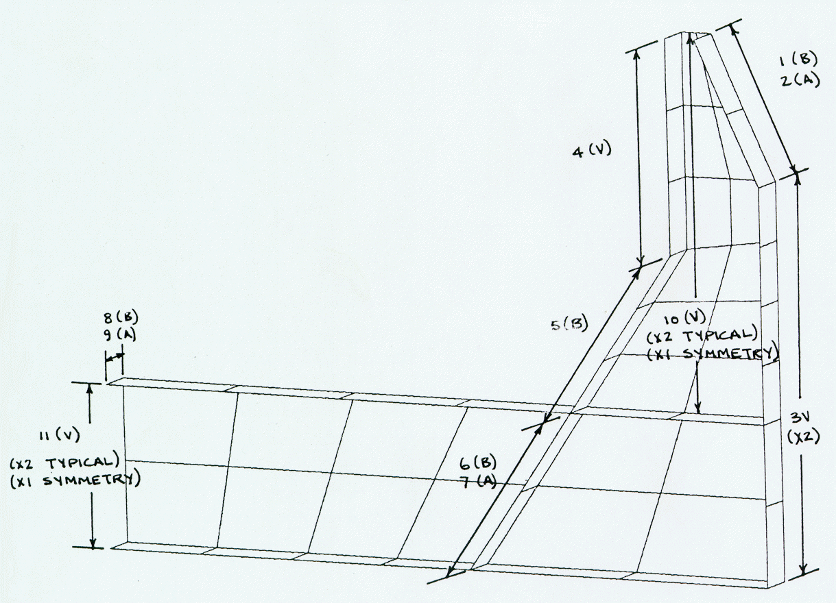
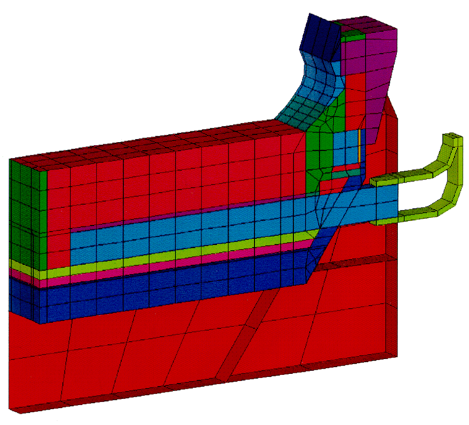
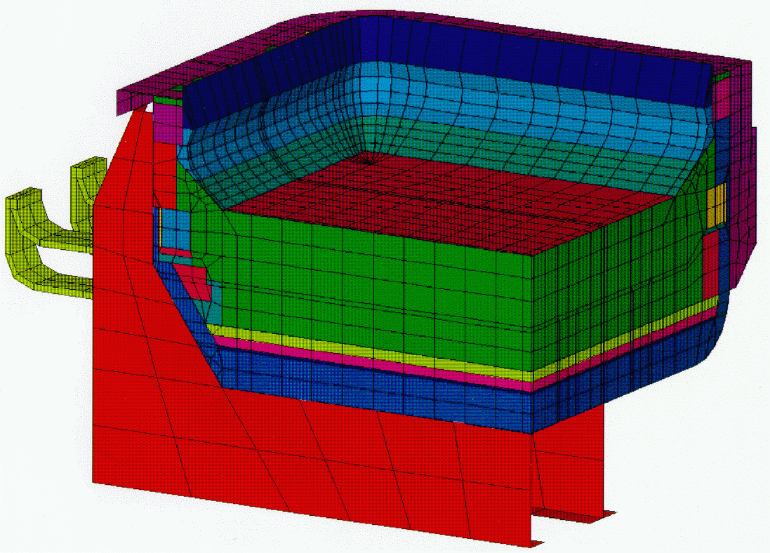
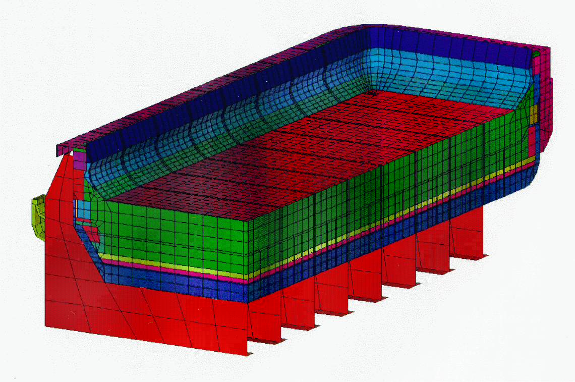
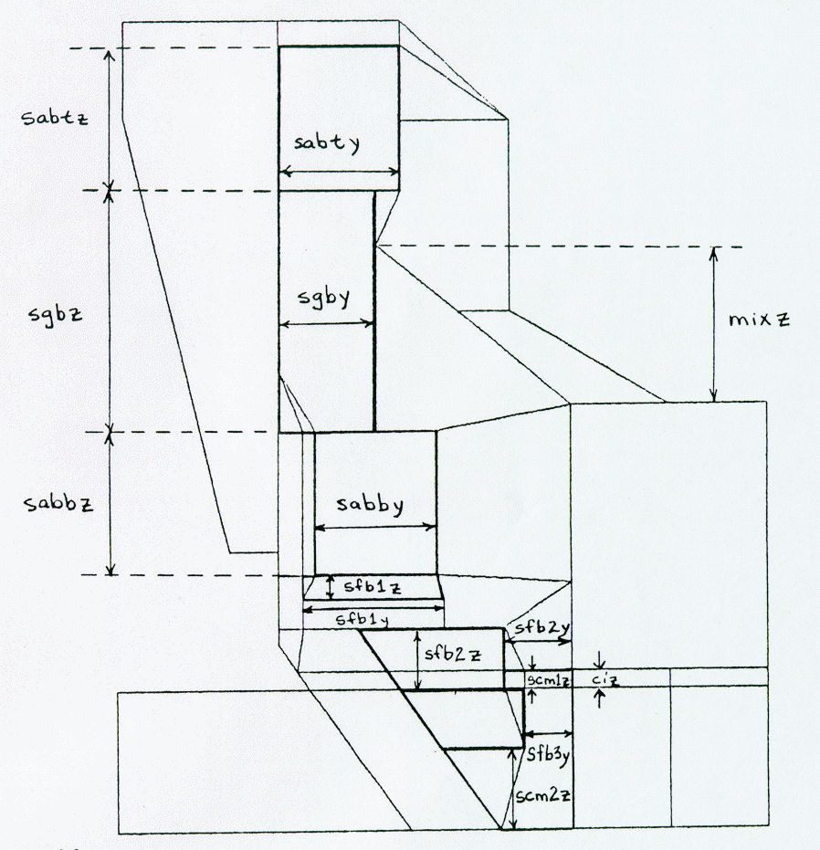
The geometric symmetry of the cell made it possible to model but a quarter of the cathode. The model consists of 21387 elements (Figure2). The geometry of the shell and lining was completely and uniquely represented by 109 independent size parameters Figure 3). Furthermore, 25 materials were used, each of which was defined with non-linear, temperature dependent properties. Heat loss to the environment by convection and radiation was represented using convection
Internal View

External View

Figure 2: Quarter Model

Figure 3: Example of Size Parameters Definition

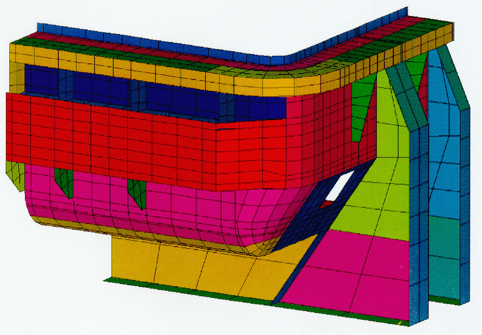
boundary conditions in the model. Thirty-three temperature dependent equivalent surface film coefficients, that represented both modes of heat transfer were used (Figure 4).

Figure 4: Example of Convective and Radiative Boundary Condition Surfaces Definition

Variable Model Size

Solving a quarter model requires 27 hours of which there are 23 CPU hours on an SGI 4D/35 workstation with 32 Mbytes of memory. Fortunately, solving a quarter model is not required for every design iteration.

In order to reduce the overall computational time, three levels of complexity were built into the model, which are:

· The first level represents a cathode slice, half a block thick, at the centre of the cell (Figure 5). Away from the corners, this basic repetitive unit is all that is required to produce accurate results. This model segment is made of 1199 elements and requires 43 minutes to compute.

Figure 5 Slice Model Segment

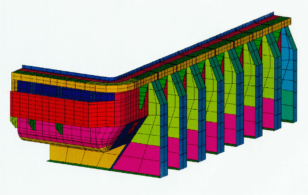
· The second level represents the cathode corner, made of only 2 full cathode blocks (Figure 6). This model segment is useful to study the effect of corner design changes on the freeze profile in the corner. It consists of 6999 elements and requires 8 CPU hours of a total of 9 hours to run.


Internal View

External View

Figure 6: Corner Model Segment

· The third level represents the full quarter model. It consists of the sum of the corner model segment and of 12 slice model segments put together. Creating a quarter model does not represent any significant extra setup work although it requires substantially more time to run. On the other hand, it opens the door to run various design changes such as studying the effect of cut-out blocks, etc.

Parametric Looping Logic

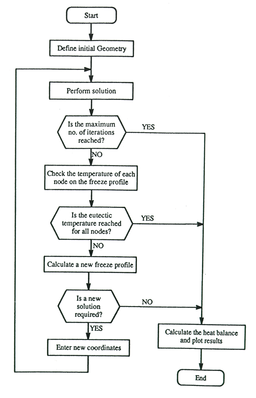
The calculation of the final freeze profile is an iterative procedure due to the non-linear aspects of the problem. The shape of the freeze profile is dependent on the surface temperature which in turn is dependent on the geometry of the model. The objective is to change the assumed geometry of the freeze profile such that all the nodes on the surface are within a prescribed tolerance of the melting temperature. This type of iterative looping is not part of the standard ANSYS non-linear capabilities. A customized solution logic was programmed using the ANSYS parametric design language (APDL). Figure 7 shows a flowchart of the looping logic as implemented in the model.

Model Results

Figure 8 shows a temperature contour plot of the converged solution for the three levels of model complexity and Table I presents the corresponding thermal summary. Ultimately, one is interested in the heat balance of the full cell. This can be calculated from the various models by appropriate scaling.

Figure 7: Flowchart of Freeze Profile adjustment Loop

The quarter model is converted into a full scale cathode heat loss:

Cell Heat Loss = 4 x 53.3 = 213.3 kW

Conversion of the slice and corner model segment heat loss into a full cell cathode heat loss is achieved by the fourfold summing of the corner model heat loss and 12 times the slice model heat value, i.e.:

Cell Heat Loss = 4 x (21.3 + 12 x 2.68) = 213.8 kW

The result is only 0.3 % higher than the quarter model result. It confirms the assumption that a slice-corner model combination is very accurate in representing the cell behavior in the center and corner respectively.

On the other hand, it is far more difficult to convert the slice submodel heat loss alone into a full cell cathode heat loss since a factor that accounts for the end wall dissipation must be used. It may be possible to estimate such a factor from experience and measurements. However, having both the quarter and the slice model heat loss results, this factor can be evaluated to be:

Sides to Cell Scale Factor = (53.3 / (16 x 2.68) = 1.24

One must use this factor with care since it will vary as design changes are made.


Slice Model
Corner Model
Quarter Model

Figure 8: Isotherms


Table I: Heat Table Summary

Slice Model Segment
Corner Model Segment
Quarter Model
Total heat input
2677 W
21273 W
53148 W
Total heat lost
2694 W
21336 W
53412 W
Total cell current
175 kA
175 kA
175 kA
Current applied in model
2734 Amps
10937 Amps
43750 Amps
Average lining voltage drop
349 mV
347 mV
349 mV
Solution error
0.65%
0.29%
0.50%

Model Calibration

Model calibration is the critical phase of any development, and the Grande-Baie model is no exception. The initial results presented here, ~215 kW of cathode heat loss and ~350 mV of lining drop, do not compare well with the experimental results obtained from thermo-electric "blitz" campaigns (~250 kW of cathode heat loss and ~320 mV of lining drop).

After the usual geometry and boundary conditions were checked, material properties had to be reviewed even if they has been successfully used in similar models [1,2]. A close look revealed that the insulating slabs, extensively used in the Grande-Baie technology, are exposed to much higher temperatures than with other cell technologies previously studied. Using data from A.T. Tabereaux [3], the conductivity of the insulation slab in the high temperature range was adjusted and the model rerun. The new results were very close to the experimental data. Furthermore, an autopsy of a cell confirmed that considerable segments of the insulating slab were destroyed during pot operation.

CONCLUSIONS

The finite element method provides an excellent tool for the optimum retrofit design of an aluminum reduction cell. The commercial program ANSYS was successfully used to develop a quarter thermo-electric cathode model of the Grande-Baie cell design.

After adjustment of the insulation slab thermal conductivity at high temperature, the model successfully reproduced measurements obtained from thermo-electric "blitz" campaigns.

ACKNOWLEDGEMENTS

The authors would like to thank Frederic Laroche for the "blitz" data and Steve A. Tomlinson for the autopsy data.

REFERENCES

  1. M. Dupuis, I. Tabsh, "Thermo-Electric Coupled Field Analysis of Aluminum Reduction Cells Using ANSYS Parametric Design Language", presented at the ANSYS Fifth International Conference and Exhibition, Pittsburgh, Pennsylvania, USA, May 20-24, 1991.

  2. M. Dupuis, I. Tabsh, "Thermo-Electric Analysis of Aluminum Reduction Cells", Proceedings of the 31st Annual Conference of CIM, Light Metals Section, 1992, pp. 55-62.

  3. A. T. Tabereaux, D. V. Stewart, "High-Temperature Critical Point (HTCP) for Insulating Blocks Used for Cathode Insulation", Proceedings of the 3lst Annual Conference of CIM, Light Metals Section, 1992, pp. 103-114.