MODELING GRAVITY WAVES IN AN ALUMINIUM REDUCTION CELL
WITH OPENFOAM
Marc Dupuis, Jonquière
Michaël Pagé, St-Nazaire
In recent years extensive modeling work has been done to assess if the usage of an irregular cathode
surface modifies the MHD stability of an aluminium reduction cell. Two types of studies have been carried
out: full 3D steady-state analysis and shallow layer 2D transient analysis. Neither type of analysis is well
suited to examine the effect of an irregular cathode surface on the cell stability.
The present work proposes a new method to analyse this stability problem. Lateral gravity waves were
simulated in a 3D lateral slice of an aluminium reduction cell. The model was solved by using the VOF
formulation of the OpenFOAM code. Results of the evolution of the bath-metal interface are presented for
a reduction cell having different types of irregular surfaces. That evolution is compared to the flat cathode
surface case; irregular surfaces provided little extra damping of the gravity waves.
Introduction
The irregular cathode surface technology is under continual development in China [1]. A recent Chinese
paper outlined a detailed 3D model based on ANSYS and CFX solvers [2]. Steady-state solutions were
presented for a reduction cell with either a flat or an irregular cathode surface. Both MHD and gas release
under the anodes were driving the fluid motion. The steady-state results of the 3D model with irregular
cathode surface clearly demonstrated, that the bath and metal flows were three-dimensional in nature (see
Figure 12b of [2]).
Studies using a 2D transient model (MHD-Valdis) with bath and metal flows in two horizontal shallow
layers could not identify any significant impact of an irregular cathode surface on the cell stability [3, 4, 5,
6]. This suggests that either using irregular cathode surface do not affect cell stability or that it is the three
dimensional flows introduced by irregular cathode surface and not taken into account by MHD-Valdis that
affects the cell stability. Despite that limitation, MHD-Valdis remains an efficient stability analysis tool for
standard cells with a flat cathode surface where the flows are essentially two dimensional in nature.
Since the bath-metal interface motion is a time dependant phenomenon, a cell stability analysis should be
based on a transient model. The above remarks indicate that in the case of irregular cathode surface, the
model should also be in 3D since this type of cathode surface generates three-dimensional flows.
A new modeling approach
The variable Lorentz forces in the metal pad of a reduction cell drive the fluid movements and the viscous
damping reduces the fluid movements [7, 8]. The aim of an irregular cathode surface would be to increase
the viscous damping in the metal and thereby to enhance cell stability.
For a bath-metal interface to move around the cell, both the molten metal and the bath must be displaced.
Since the bath layer thickness under the anodes is much less than the metal pad thickness, the speed of the
bath flow has to be greater than the speed of the metal pad flow. Hence viscous damping in the bath is very
important to the bath-metal interface wave dynamic and must also be considered.
In view of the limitations of the models presently used for stability analysis of reduction cells with irregular
cathodes surfaces, a new modeling approach was developed and tested. The new approach used a transient
3D model consisting of a lateral slice through a reduction cell. The bath and molten metal were subjected to
lateral gravity waves by initially inclining the bath-metal interface. The cathode surface was either flat or
with different versions of irregularities. The speeds of the bath and metal layers and the movement of the
bath-metal interface were calculated over time.
Selection of a proper numerical code to simulate a free interface wave
Only a few codes are able to cope with the physic of the proposed model, which is a transient 3D multi-
phase flow problem; the open source code OpenFOAM is one of them. OpenFOAM has become a popular
code in many applications due to its free surface modeling capabilities [9], which are comparable to other
VOF solvers like CFX [10].
The motion of the free interface between two immiscible liquids in a closed rectangular container has been
studied experimentally in a physical model. Figure 16 of [11] shows the gravity driven interface motion
between two liquids in a closed container. However, such measurements are difficult to reproduce
accurately [12]. This type of free surface wave was successfully modeled by using the OpenFOAM code
[13]. Flows around obstacles like those added to the cathode surface have also been modeled successfully
by using the OpenFOAM code [14].
A similarity between these above described problems successfully solved by OpenFOAM and the gravity
driven bath-metal interface wave in a reduction cell problem suggests that the use of OpenFOAM code is
appropriate for solving the proposed lateral slice model.
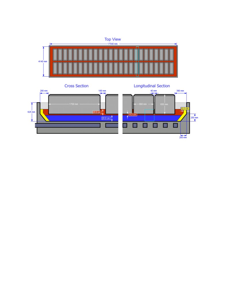
Setup and solution of the lateral slice model
The lateral slice model geometry is based on the cross-section of the GY420 cell design [15]. Different
views of the cell design are shown in Figure 1, which was produced from the Peter Entner CellVolt
application [16]. A fairly standard bath composition was selected for this study (see Figure 4 of [17]).
The model depth (300 mm) extended from the front frictionless symmetry plane located at half the anode
width to the back frictionless symmetry plane located at half the anode width between two adjacent anodes.
The length (3940 mm) of the slice model was typical of a cell cavity width of a GY420 cell less a 100 mm
uniform ledge thickness at both sides. The height of the slice model was composed of three layers: 200 mm
for the metal pad (for the flat cathode surface case), 200 mm for the bath layer and 75 mm for the air layer
on top. The anode-cathode distance (ACD) was 40 mm. The cathode surface was either flat or with
different types of irregularities. Figure 1 of [17] is showing the geometry of the flat cathode surface case
while Figure 10 of [17] is showing the geometry of the first type of cathode surface irregularity studied
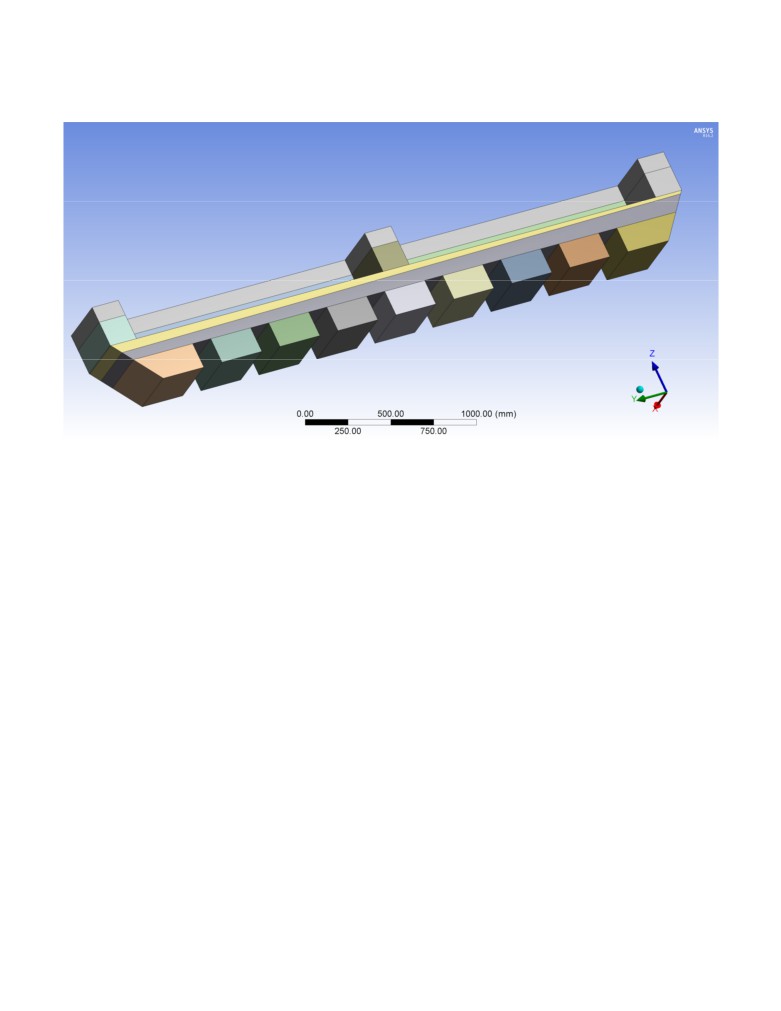
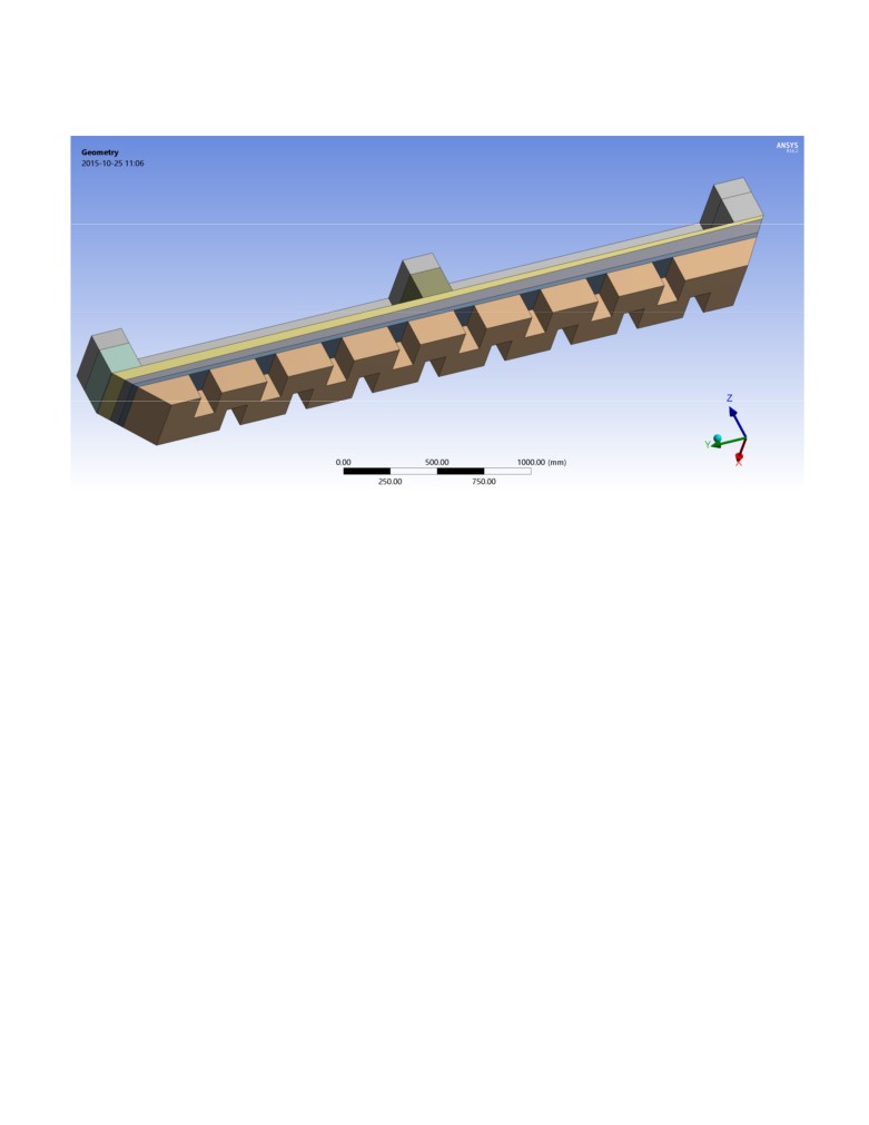
being 8 continuous longitudinal ridges 100 mm high and 200 mm wide. Figures 2 to 4 are presenting the
geometry of three new types of cathode surface irregularities studied next, namely
8 continuous
longitudinal ridges 160 mm high and 125 mm wide, 16 discontinuous and alternating longitudinal ridges
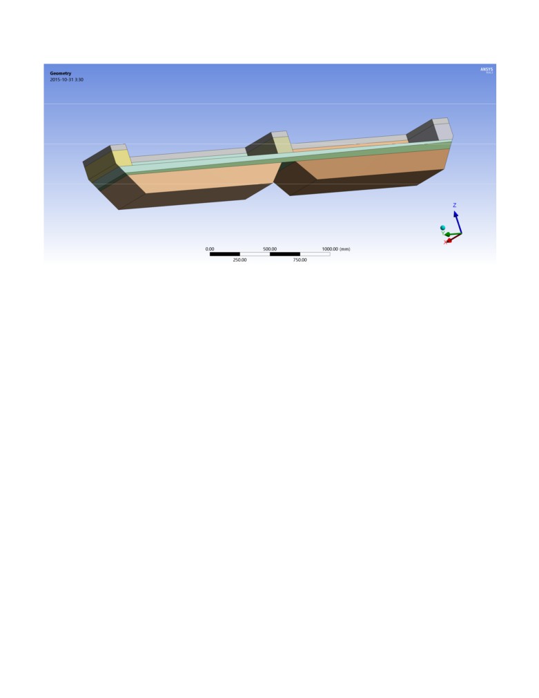
160 mm high and 125 mm wide and a single trapezoidal continuous longitudinal ridge located under the
center channel leaving only 4 cm of metal pad thickness under that channel. In all the cases studies, the
metal pad volume remained unchanged.
The mesh of the different lateral slice model versions consisted of about 1 175 000 hexagonal finite
volumes of fairly uniform size with an orthogonal quality of around 0.77 (see Figures 3 and 11 of [17]).
The mesh density was somewhat coarser than the one used in a wind engineering study [14]. However, it
was fine enough to resolve the boundary layer at the solid surfaces (cathode, anode and ledge) fairly well.
The mesh was perfectly aligned with the initial position of the bath-metal interface in order to ensure a
smooth start of the transient solution.
The transient solution was started with a sloped bath-metal interface of -20 mm on the left side and +20
mm on the right side of the lateral slice model. The motion of the fluids was calculated using an explicit
solver available in the OpenFOAM 2.3.0 code [18]. The multiphase Euler solver was used with a
maximum Courant Number of 0.05 and maximum time step of 0.02 seconds. Because of its demonstrated
ability to predict viscous drag fairly well, the k-ω SST (shear stress transport) turbulence model was used in
the flow calculation [19]. Continuity of the velocity was assumed at the bath-metal interface.
The transient calculations were made for a total of 60 seconds, which allowed about three oscillations of
the bath-metal interface. The calculations were performed on a DELL Xeon ES-2697 V3 computer having
128 GB of RAM and 28 cores. The computer took about 30 CPU hours to calculate that transient solution
using all 28 cores.
Solution of the “reference” flat cathode surface model
The solution of the “reference” flat cathode surface model is presented in Figures 6 to 9 of [17]. The
positions of the bath-metal interface are shown at intervals of 15 seconds in Figure 6 of [17]. Figure 7 of
[17] shows the velocity field at the front symmetry plane, which passed through the anode center, after 15
seconds. The maximum bath velocity was about 30 mm/s. The bath flow entrained the top layer of the
metal and also flow reversal occurred in the metal pad. There was a horizontal plane of zero metal velocity
about 40 mm below the bath-metal interface. After 60 seconds the velocities in the bath and metal layers
were less than 5 mm/s and the motion of the bath-metal interface was almost completely damped (see
Figure 8 of [17]).
The maximum turbulent viscosity (Figure 9 of [17]) in the metal pad was 4.66x10⁻⁴ m2/s at 15 seconds and
was located below the center channel. This viscosity was 1447 times higher than the laminar viscosity of
molten metal at 3.22x10⁻⁷ m2/s.
Solution of the 8 continuous rectangular 100x200 mm ridges model
Apart from the shape of the cathode surface, most of the model dimensions were kept the same as those of
the “reference” flat cathode surface model. However, the metal pad was raised by 41.5 mm, in order to
maintain the same mass of metal considering the presence of the 8 continuous rectangular 100x200 mm
ridges.
The solution of this first irregular cathode surface model is presented in Figures 13 to 15 of [17]. Figure 15
of [17] shows the position of the bath-metal interface every 15 seconds. Figure 13 of [17] shows the
velocity field in the same front symmetry plane as Figure 7 of [17] also after 15 seconds. Due to the
presence of the cathode ridges, which acted like flow obstacles, the bath flow and especially the metal flow
were now quite different. The bath velocity was reduced in most bath regions and the metal pad had local
regions of high and low velocities near the cathode ridges. The horizontal plane of zero metal velocity was
raised towards the bath-metal interface by about 40 mm. This modified flow field could translate into
higher current efficiency.
The maximum turbulent viscosity (Figure 14 of [17]) was reduced to 3.85x10⁻⁴ m2/s and occupied a much
smaller area beneath the center channel. These results seem to suggest some stabilization of the bath-metal
interface.
Solution for the 8 continuous rectangular 160x125 mm ridges model
Since [17] was written, three new models testing different types of cathode surface irregularities were
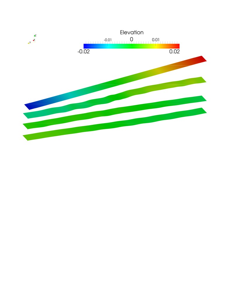
constructed and solved (see Figures 2 to 4). Figure 5 shows the position of the bath-metal interface for that
model at intervals of 10 seconds from 0 to 30 seconds for the model with 8 continuous rectangular 160x125
mm ridges. The interface is not significantly moving after that.
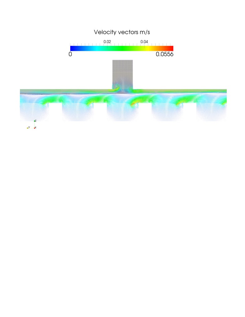
Figure 6 presents the velocity field in the front symmetry plane after 10 seconds for that same model. Due
to the presence of the much higher ridges, the maximum velocity is now located in the metal pad, and the
horizontal plane of flow reversal has essentially moved to the bath-metal interface. For that reason, this is
possibly an improvement over the previous model solution with 8 continuous rectangular 100x200 mm
ridges.
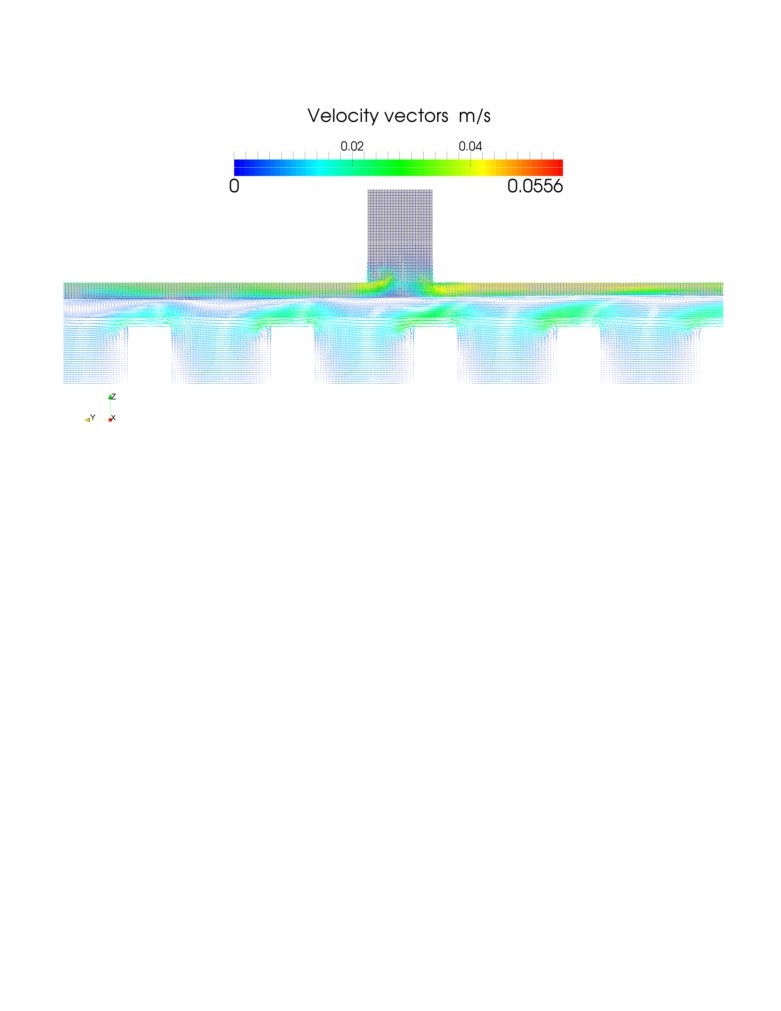
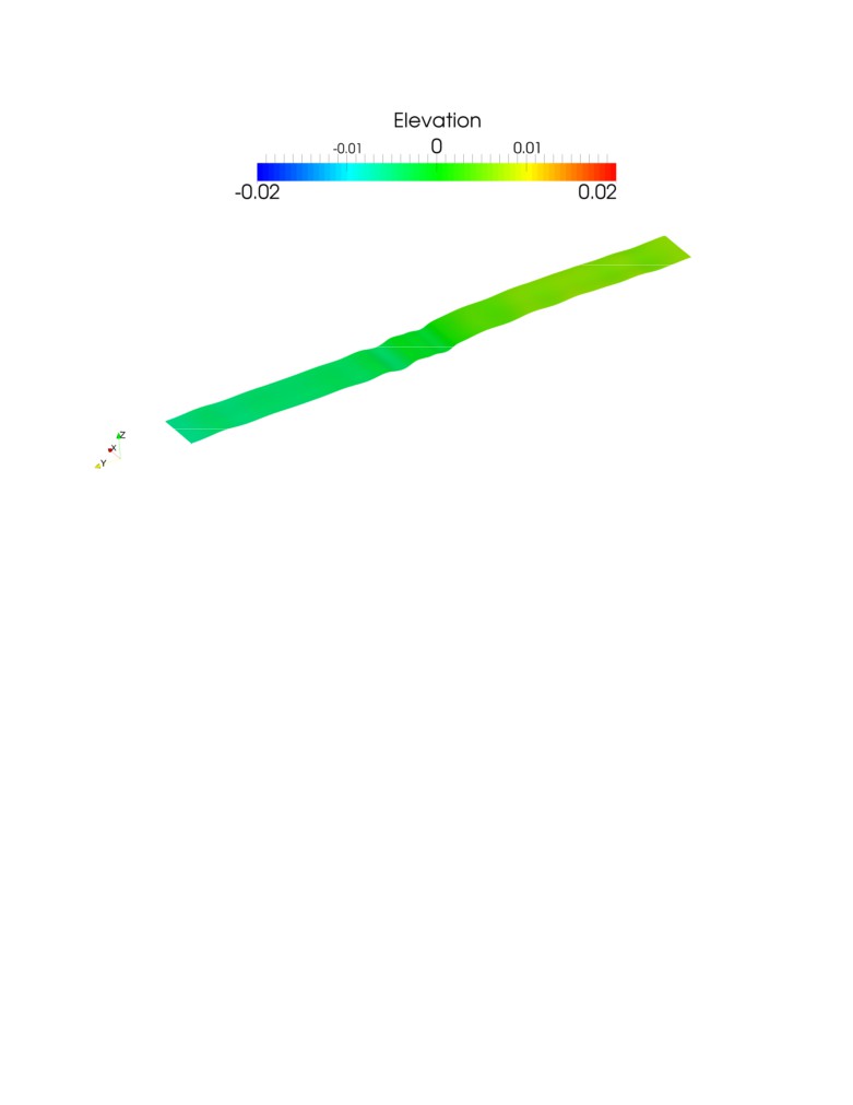
Solution for the 16 discontinuous alternating rectangular 160x125 mm ridges model
The next model wants to test if using discontinuous alternating ridges would constitute an improvement
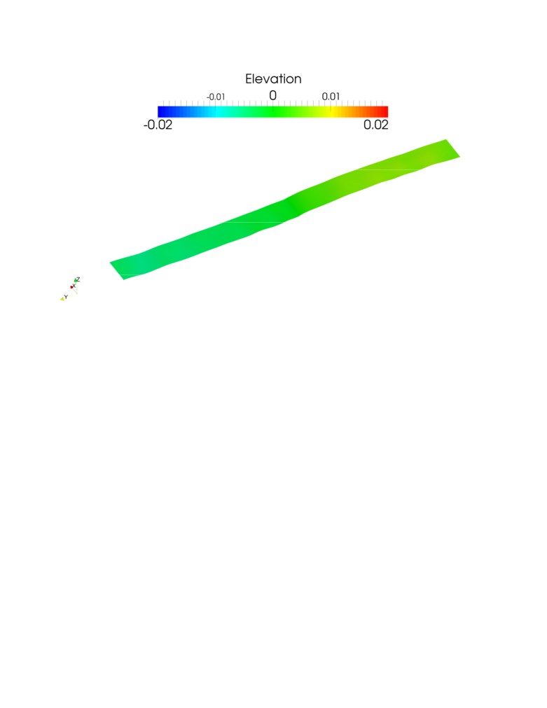
over continuous ridges. Figure 7 shows the position of the bath-metal interface for that model after 10
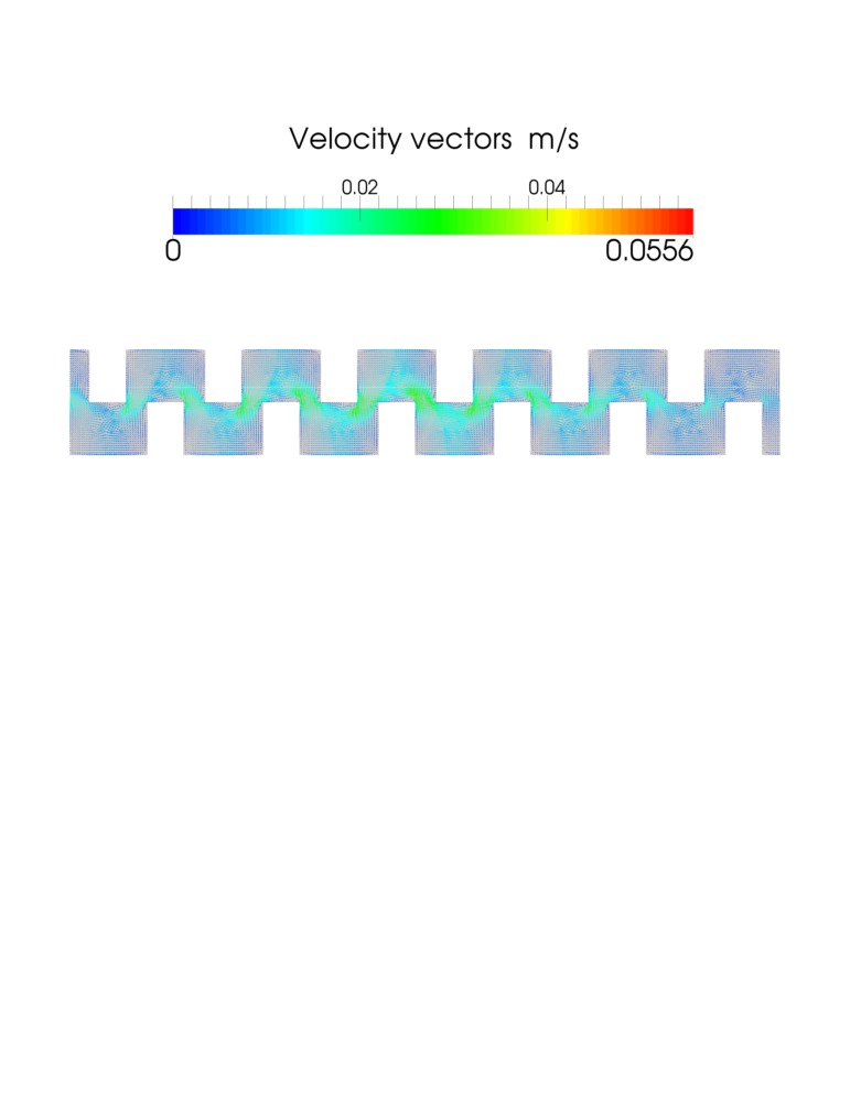
seconds from the same starting point as all the previous cases. Figure 8 shows the metal pad velocity field
in a horizontal plane located 80 mm above bottom of the metal pad which is at the ridges mid height after
10 seconds. The metal flow is zigzagging around the discontinuous alternating ridges which might reduce
sludge formation. Figure 9 presents the velocity field in the front symmetry plane after 10 seconds for that
same model. The maximum velocity is located in the bath and the flow reversal move back down in the
metal pad.
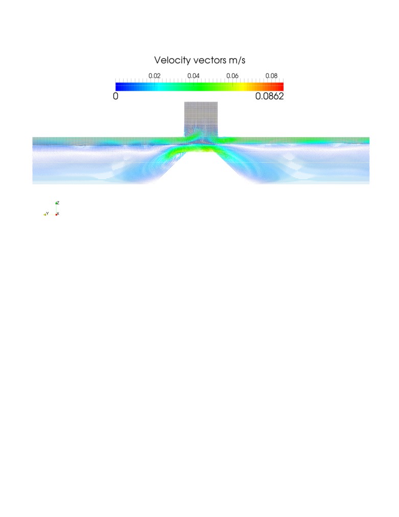
Solution for the single trapezoidal continuous ridge model
The last model aims to test a quite different type of cathode surface obstacle to the metal pad flow inspired
from the recent Alcoa patent [20]. It is a single continuous longitudinal obstacle located under the center
channel. A trapezoidal shape was selected this time, the top section is almost as wide as the center channel
itself and there is only 4 cm of metal pad thickness left above it (see Figure 4).
Figure 10 shows the position of the bath-metal interface for that model after 10 seconds from the same
starting point as all the previous cases. Figure 11 presents the velocity field in the front symmetry plane
after 10 seconds for that same model. The maximum velocity is in the meal pad above the trapezoidal
ridge.
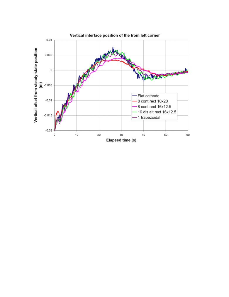
Comparison of the damping rate
There was very little difference between the interface positions evolution for all the five cases modeled.
Only the intensity of the small ripples on the interface varies from case to case. The amplitude of those
small ripples increase when the top of continuous ridges get closer to the interface position.
The dynamic bath-metal interface position at the front left corner for all five models presented in Figure 12
was more revealing. There were clearly 2 families of curves. The evolution of corner position of the single
trapezoidal continuous ridge case and the 16 discontinuous alternating ridges case is very close to the
evolution of the
“reference” flat cathode surface case. For the two remaining cases, namely the
8
continuous rectangular ridges, there was less overshoot for the two oscillations at 26 and 45 seconds. There
were also less secondary ripples of the bath-metal interface for that second group. Yet, or all 5 cases, the
same interface positions were obtained at the same time after 50 seconds.
Clearly the presence of 8 continuous rectangular ridges had some effect on the bath-metal interface
dynamic evolution. It can also be argued that the 160x125 mm ridge size is very slightly more effective
than the 100x200 mm ridge size yet those higher and narrower ridges might erode faster.
Future work
The result of the
3D transient lateral slice model demonstrated that continuous longitudinal ridges
stabilized the bath-metal interface somewhat. Thus additional studies seem to be warranted:
a) Optimize the mesh size, time step, Courant Number, turbulence model, etc.
b) Further explore different dimensions of the rectangular ridge
c) Further explore other ridge shapes like triangular or semi-circular
d) Develop a 3D transient model of the entire reduction cell
The GY420 cell design has 48 anodes. Thus a 3D transient model of that entire cell would be about 50
times bigger than the present 3D transient lateral slice model. The bath and metal layers would be subjected
to time varying MHD Lorentz forces in addition of the constant gravity forces. Constant gas release drag
forces could also be added to the bath layer.
It has already been demonstrated that the OpenFOAM code can handle MHD flows successfully [21, 22]. It
is expected that a 3D transient OpenFOAM VOF formulation based cell model would be an excellent tool
for the analysis of cell stability especially to study the impact of irregular cathode surfaces. The computing
time on the same DELL Xeon ES-2697 V3 computer would be about 1500 CPU hours or about two
months. Clearly using an even faster computer with more than 28 cores would be required in order to
reduce the turn around time. Even nowadays, CPU resources are still too expensive to be able to carry out
such 3D transient cell stability analysis without a very significant R&D budget.
Conclusions
Lateral gravity waves were successfully simulated in a 3D transient slice model of a reduction cell. The
effect of the cathode surface on the bath-metal interface was investigated. The results showed that multiple
continuous longitudinal ridges promote some level of extra wave damping while other types of irregular
cathode surface irregularities have no observable impact.
The lateral slice model was solved using the VOF formulation in the OpenFOAM code on a DELL 28
cores Xeon ES-2697 V3 computer having 128 GB of RAM at its disposal. The calculation took about 30
CPU hours to calculate the transient evolution of the bath-metal interface during 60 seconds.
References
[1] N. X. Feng: Low Energy Consumption Aluminum Reduction Cell with Novel Cathode, China, ZL
200710010523.4, 2008.
[2] Q. Wang, B. Li, Z. He and N. Feng,
“Simulation of Magnetohydrodynamic Multiphase Flow
Phenomena and Interface Fluctuation in Aluminum Electrolytic Cell with Innovative Cathode”,
Metallurgical and Materials Transactions B, Vol. 45B 2014, 272-294.
[3] M. Dupuis and V. Bojarevics, “Non-linear Stability Analysis of Cells Having Different Types of
Cathode Surface Geometry”, TMS Light Metals 2015, 821-826.
[4] M. Dupuis and V. Bojarevics, “Influence of the Cathode Surface Geometry on the Metal Pad Current
Density”, TMS Light Metals 2014, 479-484.
[5] M. Dupuis and V. Bojarevics, “Newest MHD-Valdis Cell Stability Studies”, Aluminium, 90 (2014) 1-
2, 42-44.
[6] V. Bojarevics, “MHD of Aluminium Cells with the Effect of Channels and Cathode Perturbation
Elements,” TMS Light Metals 2013, 609-614.
[7] N. Urata, “Wave Mode Coupling and Instability in the Internal Wave in the Aluminum Reduction
Cells”, TMS Light Metals 2005, 455-460.
[8] P. Davidson, “An Introduction to Magnetohydrodynamics”, Cambridge Texts in Applied Mathematics,
Cambridge University Press 2001, 363-386.
[9] H. Jasak, “OpenFOAM: Introduction, Capabilities and HPC Needs”, Cyprus Advanced HPC Workshop
Winter 2012.
[10] S. Hansch, D. Lucas, T. Hohne, E. Krepper and G. Montoya, “Comparative Simulations of Free
Surface Flows Using VOF-Methods and a New Approach for Multi-Scale Interfacial Structures”,
Proceedings of the ASME 2013 Fluids Engineering Division Summer Meeting.
[11] S. Y. Lee1, C. E. Park and V. H. Ransom, “On The Gravity Driven Force Terms of Single Pressure
One-Dimensional Multi-Fluid Flow Model in Horizontal Channel and Their Validation”, Proceedings of
ICAPP 2013 Jeju Island, Korea, April 14-18, 2013.
[12] D. R. Howell, B. Buhrow, T. Heath, C. McKenna, W. Hwang and M. F. Schatz, “Measurements of
Surface-wave Damping in a Container”, Physics of Fluids, Vol. 12, no 2, February 2000, 322-326.
[13] G. C. J. Morgan, “Application of the InterFoam VOF Code to Coastal Wave/Structure Interaction”,
Ph. D. thesis, University of Bath, Department of Architecture and Civil Engineering, September 2012.
[14] I. Lindmeier, C. Heschl, G. Clauss and U. Heck, “Prediction of the Flow Around 3D Obstacles Using
Open Source CFD-Software”, The Fifth International Symposium on Computational Wind Engineering
(CWE2010) Chapel Hill, North Carolina, USA May 23-27, 2010.
[15] Ji-lin DING, Jie LI, Hong-liang ZHANG, Yu-jie XU, Shuai YANG and Ye-xiang LIU, “Comparison
of Structure and Physical Fields in 400 kA Aluminum Reduction Cells”, J. Cent. South Univ., (2014) 21,
4097−4103.
[17] M. Dupuis and M. Pagé, “Modeling Gravity Wave in 3D with OpenFOAM in an Aluminum
Reduction Cell with Regular and Irregular Cathode Surfaces”, TMS Light Metals 2016, to be published.
[19] F. R. Menter, “Review of the Shear-stress Transport Turbulence Model Experience from an Industrial
Perspective”, International Journal of Computational Fluid Dynamics, Vol. 23, No. 4, April-May 2009,
305-316.
[20] Y. Ruan and al., “Apparatus and Method for Improving Magneto-Hydrodynamics Stability and
Reducing Energy Consumption for Aluminum Reduction Cells”, US patent 2013/0032486 A1, 2013.
[21] A. Panchal, “Study of Liquid Metal MHD Flows Using OpenFOAM”, AE 494:BTP Stage 2, Dept. of
Aerospace Engineering, IIT Bombay.
[22] E. Mas de les Valls, “Development of a Simulation Tool for MHD Flows under Nuclear Fusion
Conditions”, Ph. D. thesis, Dept. of Physics and Nuclear Engineering Universitat Polit`ecnica de Catalunya,
October 2011.
Authors
Dr. Marc Dupuis is a consultant specialized in the applications of mathematical modeling for the
aluminium industry since 1994, the year when he founded his own consulting company GeniSim Inc
(www.genisim.com). Before that, he graduated with a Ph.D. in chemical engineering from Laval University
in Quebec City in 1984, and then worked 10 years as a research engineer for Alcan International. His main
research interests are the development of mathematical models of the Hall-Héroult cell dealing with the
thermo-electric, thermo-mechanic, electro-magnetic and hydrodynamic aspects of the problem. He was also
involved in the design of experimental high amperage cells and the retrofit of many existing cell
technologies.
Michaël Pagé is specialized in mechanical engineering in the field of numerical simulation. Graduated from
the University of Quebec at Chicoutimi in 2006, he has since worked in digital simulation for engineering
as well as product development firms. His professional experience and his personal interest in simulation
have enabled him to acquire a remarkable mastery of this technology. His technical versatility allowed him
to participate in several projects in the hydroelectric field in Quebec and abroad. Since 2013, he is one of
the leaders of Simu-K inc., a company that offers services in digital simulation. This new challenge allows
him to work with companies that are experts in their field to produce innovative solutions for their
customers.
Figure 1: Sketch of the GY420 cell design
Figure 2: Model geometries with 8 continuous longitudinal ridges 160 mm high and 125 mm wide
Figure 3: Model geometries with 16 discontinuous and alternated longitudinal ridges 160 mm high and 125
mm wide
Figure 4: Model geometries with a single trapezoidal continuous longitudinal ridge located under the center
channel
Figure 5: Position of the bath-metal interface every 10 seconds from 0 on top to 30 seconds on bottom for
the model with 8 continuous rectangular 160x125 mm ridges
Figure 6: Velocity field in the front symmetry plane after 10 seconds for the model with 8 continuous
rectangular 160x125 mm ridges
Figure 7: Position of the bath-metal interface after 10 seconds for the model with 16 discontinuous
alternating rectangular 160x125 mm ridges
Figure 8: Velocity field at the ridges mid height horizontal plane after 10 seconds for the model with 16
discontinuous alternating rectangular 160x125 mm ridges
Figure 9: Velocity field in the front symmetry plane after 10 seconds for the model with 16 discontinuous
alternating rectangular 160x125 mm ridges
Figure 10: Position of the bath-metal interface after 10 seconds for the model with a single continuous
trapezoidal ridge
Figure 11: Velocity field in the front symmetry plane after 10 seconds for the model with a single
continuous trapezoidal ridge
Figure 12: The dynamic bath-metal interface position at the front left corner for all five models