derived design charts for cylindrical connectors, the influence of
flutes and other design features still proved elusive.
Intuitively, adding more surface area by adding flutes or
increasing their length should reduce the voltage drop. A trial
using such a design ("instrumented anode 2" in [7]) has however
yielded a higher voltage drop than the original design
("instrumented anode 1" in [7]).
The numerical investigations of Hou et al (12) did not allow any
clear conclusion to be drawn. The limitation of the approach used
in the numerical models assumed the contact resistance at the
interface constant and independent of pressure or temperature.
Also, the cast iron connector was assumed to establish contact
with carbon on its entire surface, which in reality might not be the
case. Furthermore, no experimental results were presented as a
validation to the models assumptions and results.
cooled, an air gap opens up between the carbon and cast iron
surfaces. The magnitude of the air gap depends notably on the
molten iron temperature at pouring, on the carbon and steel stub
temperature when the cast iron solidifies, on the cast iron
composition and on the cast iron thickness. Usually, the thicker
the cast iron, the larger the air gap.
Once set in a pot, the anode heats up and cast iron to carbon
contact is established. However, at normal operating temperatures,
the thermal expansion of the stubs and cast iron may not be
sufficient to generate enough contact pressure for a good contact
on the entire interface.
al
Analysis commercial code ANSYS [7]. From preliminary
simulations using a pie-shaped section of the steel stub-cast iron-
carbon assembly, the three main factors affecting fluted connector
performance were found to be the following:
thickness, cast iron might not make
contact with carbon on its entire surface.
This is especially true for long flutes.
resistance
further away from the steel stub the
contact occurs, the higher the contact
resistance.
radius
magnitude more conductive than carbon,
the further away from the steel stub the
contact occurs, the shorter the current path
in carbon.
from the stubs. Traditional ways of increasing (apparent) surface
area in fluted designs, like adding flutes, increasing their length or
their width, result in a larger mean diameter and a larger mean
contact resistance. Minimisation of the stub-to-carbon voltage
drop is therefore a balancing act between the real contact area and
the resulting electrical contact resistance.
Limitations in the contact mechanics algorithms used by Richard
[1,7,8] however limited the accuracy of the results and severely
constrained the meshing requirements.
thermal contact conductance, electrical contact resistance and
Joule heat generation at the interface, was developed and
implemented by Goulet [13] in the in-house finite element toolbox
FESh++ [14] using modern Object-Oriented techniques. The use
of algebraic equations to specify the material properties allows the
direct implementation of the electrical contact resistance
equations derived by Richard et al [8].
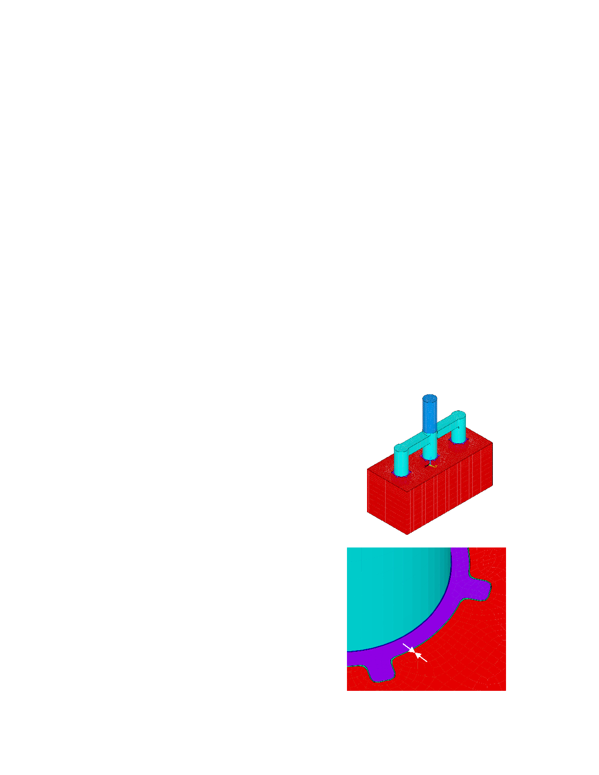
Using the same approach than Fortin et al [16], a simplified
parametric anode geometry, shown in Figure 2, was developed
and meshed with linear hexahedral elements. The geometry
includes the part of the aluminium stem, the steel yoke and stubs,
cast iron and carbon anode. For the sake of simplicity, the stub
hole vertical tapers were neglected. Geometric air gaps at the cast
iron / carbon interface are considered.
a) Simplified Anode Assembly
iron