The width of the cast iron to carbon air gap depends on the cast
iron thickness such that different gaps are considered on the
cylindrical sections and at the end of the flutes. A simplified
analytical method was used to estimate the magnitude of air gap
for moderate changes of stub hole geometry.
With the change of radius of the steel stub at cast iron
thickness and Ts the cast iron solidification temperature, the air
Mesh
The Finite Element mesh composition is summarized in Table 1.
Multiphysics contact elements are used to establish mechanical
contact at the cast iron to carbon interface, determine the contact
pressure, and transfer heat and electrical current. A typical mesh
for the cast iron is shown in Figure 3.
Material Properties
Thermal properties were estimated from Dupuis [17]. For
simplicity, all materials were considered elastic. Carbon cracking
and crushing in carbon could be taken into account by adapting
the constitutive law developed for carbon cathode material by
D'Amours et al [15].
respectively from Katus [18] and Ward [19]. Carbon elastic
properties were estimated from Richard [1,7,8].
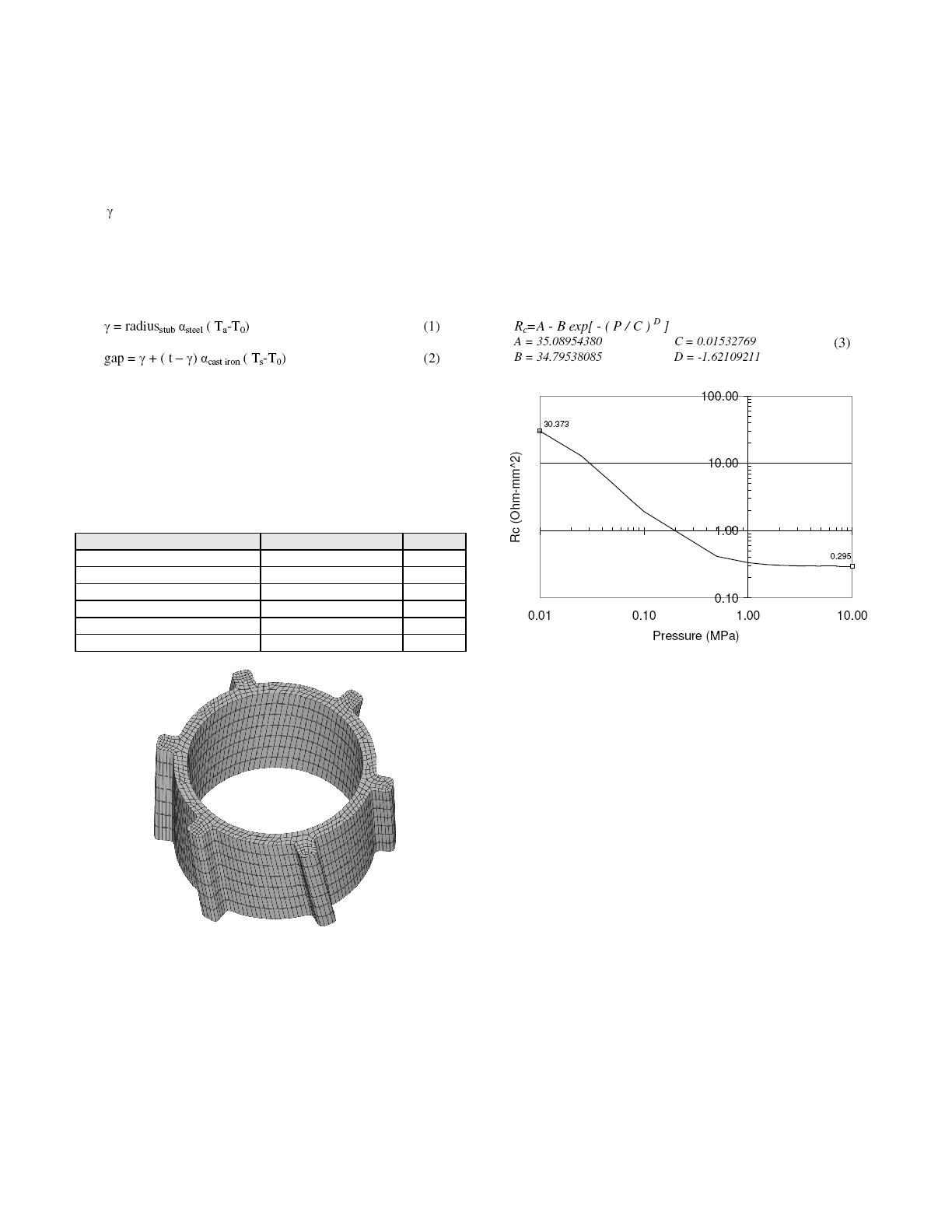
Cast iron to carbon electrical contact resistance was obtained from
[8], using a calibration based on the Brooks & Bullough data [4].
For the sake of simplicity, given the small changes of contact
resistance in the range of temperature in the stub holes at steady-
state conditions, the electrical contact resistance Rc is assumed to
vary only with contact pressure P [MPa], as defined in equation
(3). The resulting electrical contact resistance curve is shown in
Figure 4. It is assumed that no contact exist on the stub hole
bottom.
Boundary Conditions
Similar to Fortin et al [16], equivalent thermal boundary
conditions, including partial immersion of the carbon into a 955ºC
bath, were applied through effective convective heat transfer
coefficient in order to obtain a reasonable temperature field
consistent with Dupuis [17].
The immerged part of the anode was considered to be an
equipotential and a current corresponding to an operation at 330
kA with 40 anodes was forced at the top of the anode yoke
assembly.
The bottom of the anode is supported by an equivalent elastic
foundation whose stiffness was adjusted to represent the
Archimedes force. The top of the anode stem is completely fixed.
Solution Algorithm in FESh++
For efficiency reasons, the problem is split into a fully coupled
thermal-electrical sub problem and a mechanical sub problem.
The temperature field is transferred to the mechanical sub
problem as a body load. Each sub problem is non linear and
solved using a classical Newton-Raphson iterative scheme. A
successive substitution algorithm iterates between the thermal-
electrical and the mechanical sub problems until convergence.