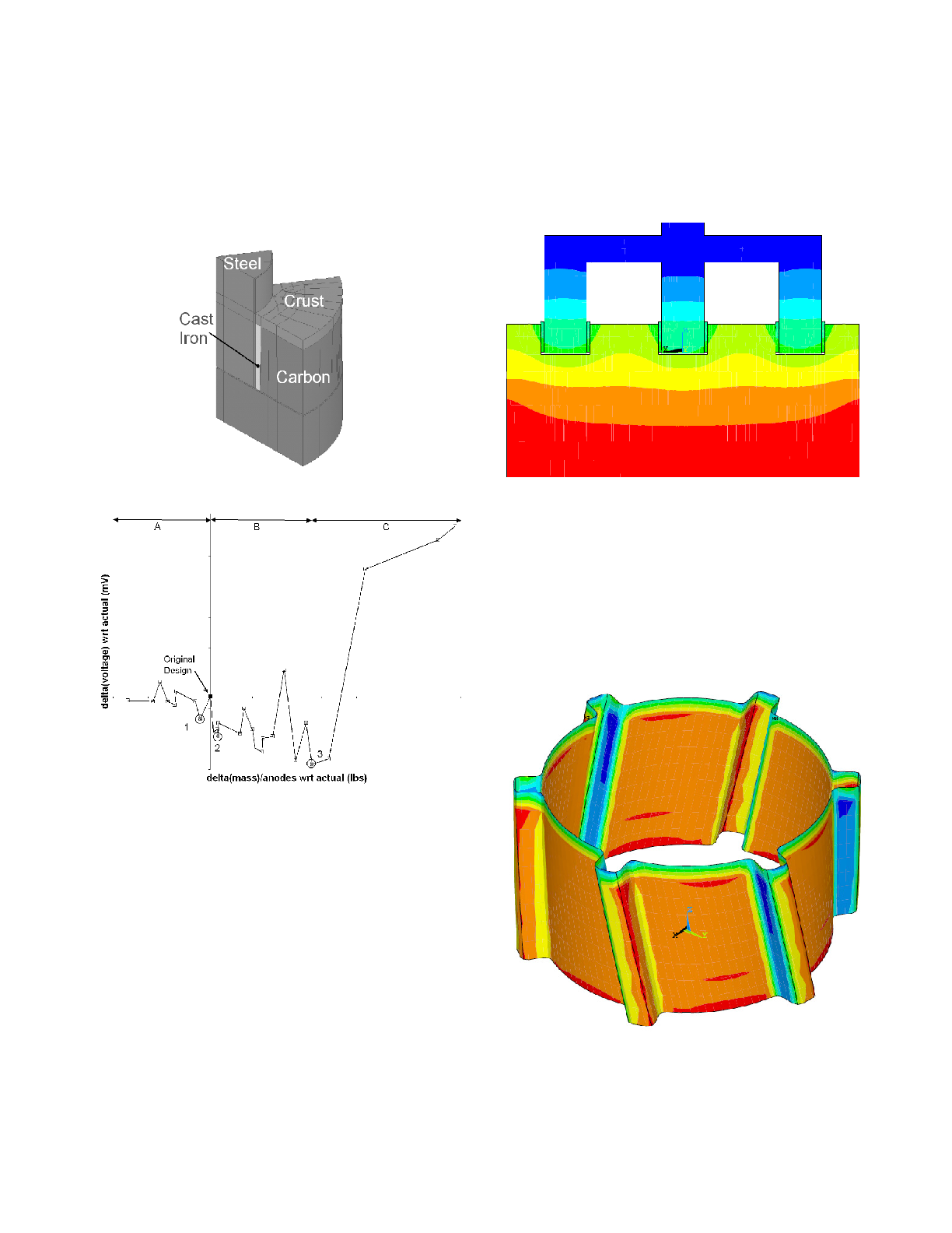
Previous work from Richard [7] using a pie shaped sub-model
(shown in Figure 5) has shown that different designs of stub holes
could result in largely different cast iron to carbon voltage drop,
as illustrated in Figure 6. In all the simulations, the cylindrical
part of the stub hole was kept constant and only the number, width
and length of flutes was varied.
It can seen that the original design was difficult to improve upon,
but that in Region A, small savings could be achieved with
slightly less cast iron (Region A, Point 1), while by adding
slightly more cast iron (Region B, Point 2), a more interesting
saving could be achieved. A minimum voltage drop was obtained
with significantly more cast iron (Point 3), which was decreasing
the rodding shop productivity to unacceptable levels. In Region C,
the contact area achieved at the end of excessively long flutes was
severely decreased such that the overall voltage drop was
increased.
These simulations were however not considering the effect of the
steel yoke expansion and the effect of gravity on the cast iron to
carbon contact established.
For the base case shown in Figure 3, gaps of 0.30 mm at the
cylindrical portion of the stub hole and 0.45 mm at the end of
flutes were obtained. Results calculated in FESh++ were
postprocessed in ANSYS. A typical temperature distribution is
shown in Figure 7. Temperatures in the order of 650ºC were
obtained in the bottom of the stub hole.
Typical results from the full anode model indicate a higher contact
pressure on the cylindrical part of the cast iron, with a moderate
pressure on the exterior side of the flute due to gravity, and a
lower pressure on the flute tip due to the larger air gap. This is
illustrated in Figure 8. As expected, the resulting current density
in the carbon, shown in Figure 9, indicates that more current is
drawn in the bottom of the stub hole and in the regions of large
contact pressure.