to help locate the busbars around the cell in a way that leads to the
generation of a magnetic field inside the cell that itself leads to a
stable cell operation.
current density in the metal pad is also extremely important and can
only be achieved with a correct busbar network sizing.
of MHD-Valdis to help design a well balanced busbar network.
uniform current pick up in all the collector bars of a modern side by
side high amperage aluminum electrolysis cell, while known to be
critical to the cell MHD stability, is not often discussed in the
literature.
computer code called respectively NEWBUS and BUSCAL
designed specifically to do such a task. Both use a simple 1D line
busbar network representation, a temperature dependent electrical
resistivity and solve for the resulting non-linear problem by
computing the voltage and temperature equations iteratively and
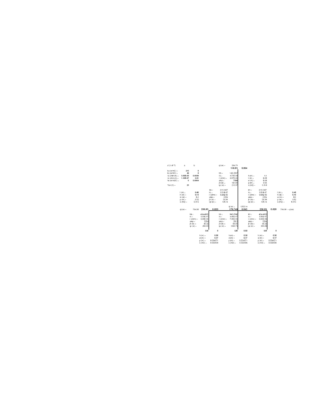
alternately until convergence is reached. These days, such an in-
house solver can be setup fairly rapidly in an Excel spreadsheet
(see figure 1).
and the different currents in the busbar network are then transferred
to the metal pad current density solver and the metal pad magnetic
field solver in preparation to run the MHD wave stability solver.
order to very accurately compute the metal pad current density field
considering both the converged steady-state ledge profile and the
busbar design. Of course, once developed, the 3D busbar model
can also be solved stand-alone.
and rod implemented in an Excel spreadsheet.
a simplified 1D line network busbar representation and use that
tool to perform busbar sizing optimization and, on the other hand,
it is possible to develop an ANSYS® based parametric 3D busbar
5 and 10] which is a commercially available, fully non-linear MHD
cell stability solver. The fact that it is fully non-linear, means that it
is solving among other variables the busbar network current
distribution at each time step. It is doing so using a versatile 1D
line network busbar generator and solver called BUSNET also
available to carry out busbar sizing optimization studies.
most efficient tool to carry out busbar sizing optimization studies,
but before proceeding with the comparison exercise, it is important
to take a step back and first review the background theory of the
equations that need to be solved.