MODELING OF ALUMINUM REDUCTION CELLS USING FINITE ELEMENT ANALYSIS TECHNIQUES

Imad Tabsh, COMPUSIM Inc.
1003D 55 Avenue N.E., Calgary, Alberta, Canada  T2E 6W1

Marc Dupuis, GéniSim
3111 Alger, Jonquière, Québec, Canada  G7S 2M9

Abstract

Finite element analysis (FEA) techniques are used extensively in industry to design new products and process vessels and to better understand the behavior of existing ones. This paper summarizes the authors' experience in using FEA to model Hall-Héroult reduction cells. FEA capabilities necessary to adequately simulate thermo-electric, electro-magnetic and stress fields within the cell are identified. Specific examples of models developed using the commercially available ANSYS® FEA program are discussed.

Introduction

The Hall-Héroult process is the only method used today for the industrial production of aluminum. Named after its inventors, Paul Héroult of France and Charles Hall of the USA, the process produces liquid aluminum by the electrolytic reduction of alumina dissolved into an electrolyte consisting primarily of cryolite.

The Hall-Héroult Reduction Cell

An aluminum reduction cell consists of a rectangular steel "open box" called a potshell supported by cradles and lined with refractory brick that surround the cathode carbon blocks. The lined potshell serves as the containment vessel for the electrolyte (also known as the bath) and the liquid metal being produced. A layer of frozen electrolyte (freeze) forms on the sides of the pot to protect the lining. Immersed in the bath are combustible carbon anodes suspended from a superstructure that is supported by the potshell. Figure 1 shows a schematic of a reduction cell.

Electric current is fed to the anodes via risers connected to an anode busbar. Within the cell, the current flows through the electrolyte to the metal pad and the cathode carbon and exits the cell via steel collector bars embedded in the cathode blocks. The collector bars are connected to the cathode busbars which in turn are connected to the risers of the adjacent pot. Typically, a smelter has one or more potlines each having 100-200 pots.

Design of An Optimum Reduction Cell

One of the main goals in designing a reduction cell is to reduce costs. Operating costs can be reduced by increasing pot life, reducing power consumption, improving metal quality and reducing man power requirements. Capital costs can be reduced by simplifying the cell design, reducing material requirements and reducing the building size to house the potline.
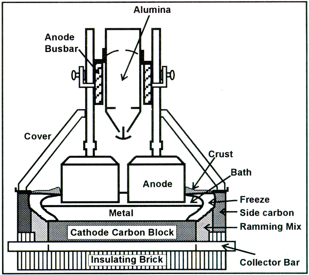
Figure 1: A schematic of an aluminum reduction cell

An optimal design of a cell requires a through understanding of the temperature and current distribution in the pot. The precise manner by which an aluminum reduction cell loses heat depends on the thermal insulation of the cell. This influences the formation of freeze which prevents early failure by erosion of the side wall. Power consumption is also affected by the thermal balance of the cell.

The current density distributions within the cell and in the surrounding busbar system generate strong magnetic fields which interact with the current distribution in the metal pad to produce Lorenz forces that induce motion of the metal. Stable operation of a cell requires a balanced busbar system and minimization of horizontal currents in the metal pad. The later are highly influenced by the shape of the freeze which in turn depends on the thermal balance of the cell.

The design of the cell is further complicated by the stresses generated in the carbon blocks and the potshell. These are due to the thermal gradients within the cell as well as the chemical loads due to the sodium diffusion into the cathode blocks and lining. The former can lead to distortion of the potshell that significantly alters the bath and metal height thus affecting the stable operation of the cell.

It can also produce plastic deformations of the potshell thus requiring major repairs for second generation pots. Large thermal gradients in the cathode blocks during preheat and startup can cause early failure of the cathode rendering the cell inoperable and creating major costs in relining and lost production. Sodium diffusion loads cause cathode failures as well as plastic deformation of the cell.

Finite Element Analysis Capabilities

It is clear from the previous discussion that the design of a reduction cell is very complex. The interaction of the various fields (thermal, electrical, magnetic and stress) makes mathematical modeling of the cell very desirable if not mandatory.

Finite element analysis (FEA) techniques are ideal for modeling of reduction cells to understand their behavior and improve on their design. Several commercial general purpose FEA codes are available on the market and have been used to model reduction cells. Furthermore, almost all aluminum companies have in-house programs customized to model particular aspects of the cell. Program capabilities necessary for adequate modeling of cells as well as the benefits of in-house versus commercial codes will be outlined in the following sections.

FEA Requirements

Several FEA capabilities are required to model aluminum reduction cells whether in-house or commercial programs are used. These include:

 1.  Solution Algorithms:
a. The ability to model non-linear material properties in the various fields: temperature dependent thermal conductivity, electrical resistivity and specific heat for thermo-electric analyses; plasticity for stress analyses; and ferro-magnetic material B-H curves for magnetic field calculation.
b. The availability of robust solution algorithms to solve the highly non-linear problems due to non-linear material properties and/or the field coupling. This includes automatic load stepping to improve solution efficiency.
c. The ability to perform steady-state and transient heat transfer analyses.
d. The ability to perform elastic / plastic stress analyses.
e. Special capabilities are required for magnetic field analysis. These must handle multiply connected regions in iron, far field effects and distributed currents.
f. CFD capabilities (including free surface capability) to model the motion of the metal pad and bath.
2. Coupled Field Analyses: The ability to automatically incorporate the interaction between fields greatly simplifies the analysis task. In particular:
a. Inclusion of the joule heat in thermo-electric analyses.
b. Definition of the temperature profile from a heat transfer analysis as input to a thermal stress analysis.
c. Definition of distributed currents from a thermo-electric analysis as input to the magnetic field solver.
d. Definition of the current density and magnetic field from a thermo-electro-magnetic model as input to a CFD calculation of the velocity field.
3. Pre and Post Processing: 70 to 90% of the time spent on a given analysis is dedicated to developing the model and reviewing the results. Comprehensive, flexible and efficient capabilities are essential for minimizing the time to converge on the final design. In particular:
a. Extensive graphics capabilities to review the model geometry and solution results.
b. Solid modeling capabilities that separate the definition of the structure geometry from the finite element mesh. This increases the efficiency of generating the final model.
c. The ability to easily define boundary conditions either on the solid model or the corresponding finite element mesh.
d. The ability to export analysis results to other programs.
4. Portability Across Computer Platforms: Some analyses such as magnetics and transient time history calculations are computationally intensive. They require the use of supercomputers in order to achieve adequate solution elapse times yet it would be more efficient to develop the models on workstations. Hence, it is essential to be able to move models between various computing platforms and to eliminate or minimize the effort required to do so.
5. Customization: Most FEA programs on the market are general purpose codes. In some cases the analyst needs a particular solution algorithm to meet specific problem requirements (see the freeze movement and sodium diffusion models described below). The ability to "customize" the general purpose FEA code is desirable since it eliminates the need to write special purpose in-house programs and interfaces to solve these problems.

ANSYS®, ABAQUS®, NASTRAN®, MAGNUM®, ASKA®, FIDAP®, PATRAN® and IDEAS® are some of the commercial codes that have been used in modeling various aspects of reduction cells. Only ANSYS® provides all the capabilities described above except for CFD which is available in FIDAP®.

In-House versus Commercial Codes

The authors favor the use of commercial general purpose codes over in-house programs for FEA modeling activities. Developing finite element codes draws on expertise in several fields including graphics, solid modeling and solution algorithms to name a few. Considerable resources are needed to provide efficient codes that require minimal effort for building and processing models.

Commercial software vendors have dedicated staff whose function is to develop code. Most offer state-of-the-art capabilities in modeling and solution techniques. Programs continue to evolve by adding more capability and/or improving user interfaces. The net outcome is more efficient programs that reduce the modeling time and free the engineer to concentrate on the design process.


Another advantage in using commercial codes is that some vendors have extensive quality assurance programs. They are designed to validate the code and insure that the coded algorithms are error free. This process is time consuming and is often underestimated. Validation of a particular model is the responsibility of the engineer performing the analysis.

It should be noted that commercial codes do not always offer all the capabilities required to model reduction cells. One example is the stability analysis. This particular problem is specific to the aluminum reduction cell and falls outside the scope of general purpose FEA codes. However, input to the analysis includes the magnetic field, current density distribution and the velocity field [1]. All these quantities can be easily calculated using FEA models. Special purpose interfaces are written to read FEA results and convert them into input to the custom programs.

Mixing in-house programs with commercial codes should be minimized because of the problems of creating interfaces. In particular, keeping the interface up to date with the current version of the commercial code can be difficult. Resources may not be available to update the interface or adequate documentation may not exist. When selecting a commercial code it is best to choose a program that has the ability to export data in a user defined format using standard program commands. This way the interface is automatically updated when a new version of the program is released (most new versions are upwardly compatible).

The Unified Model

Having all analysis requirements available in the same code is very desirable. It has the advantage that the user does not have to write special interfaces that read data from one program and feed it to the next. Even if a particular vendor writes the interface between his program and other codes (such as PATRAN® and IDEAS®) there remains the problem of keeping up with various versions of software and ensuring that the interface is available at the same time when new program versions are released.

Another reason for having all the capabilities in the same program is to reduce the effort of transferring data from one analysis to the other. Since the same geometry or a subset thereof is needed for all analyses, it is desirable to have a single finite element mesh. Elements are activated and deactivated as needed and results are stored in the same or compatible databases. The interaction between analysis types becomes the job of the program developer rather than the engineer.

One disadvantage of using general purpose programs is the time spent in becoming proficient with a particular program and to keep up to date with new releases. In some cases sufficient activity exists within a company to hire and maintain engineers whose main function is modeling. Part of their function is to keep up to date with new developments in the field. Alternatively, consultants are hired to work on particular problems as and when they arise.

A third option would be to "customize" the general purpose programs by building custom models that address particular problems. Such programs buffer engineers from the need to learn and keep up to date with commercial codes yet provide them with the full capability of these packages. Graphical user interfaces can be used to define the particular geometry of the problem at hand and the necessary operating data. The job of building the model, performing a solution and post processing the results can be automated so that the engineer can focus on the design activity. However, sufficient documentation should be provided to ensure that the engineer is fully aware of the assumptions used in the model in order to be able to evaluate the analysis results.

Examples

The following sections describe the authors' experience in using the ANSYS® program to model four aspects of reduction cells. The material presented here is extracted from publications at previous conferences. A brief summary is presented and the reader is referred to the appropriate proceedings for more details.

Freeze Movement Model

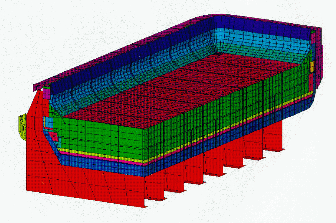
As mentioned earlier, the heat balance within a reduction cell influences the energy consumption and the formation of freeze as a protective layer on the side wall carbon. Several thermo-electric models have been developed [2,3] to predict the freeze profile in a reduction cell and evaluate the impact of changes in the lining and/or the operating conditions. The model shown in figure 2 is an example where the parametric capabilities of ANSYS® were used to develop an iterative algorithm that allows for automatically changing the freeze geometry to satisfy a predefined temperature criterion on the freeze surface. The ANSYS® parametric design language was also used to define the geometry of the model thus enabling sensitivity studies with minimal effort.

Figure 2: Thermo-electric model to predict the freeze profile.


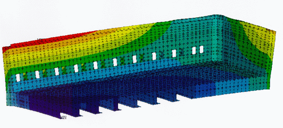
Figure 3: Stress and deflection distribution due to sodium diffusion loads.

Sodium Diffusion Model

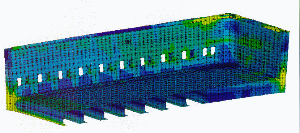
During operation of a reduction cell, sodium ions present in the bath diffuse into the cathode carbon and the surrounding brick. This leads to swelling of the carbon and can introduce large stresses in the potshell. The degree of swelling was described by Dewing [4] as a function of the state of stress in the carbon and the diffusion rate. The complex non-linear interaction between the potshell and the lining was modeled [5]. A special iterative algorithm was developed to represent the material behavior. The stress analysis accounted for the plastic deformation of the cell under load (see figure 3) and the analysis results compared favorably with field measurements. The technique provides an efficient tool to help in the design of a potshell.

Coke Preheat Model

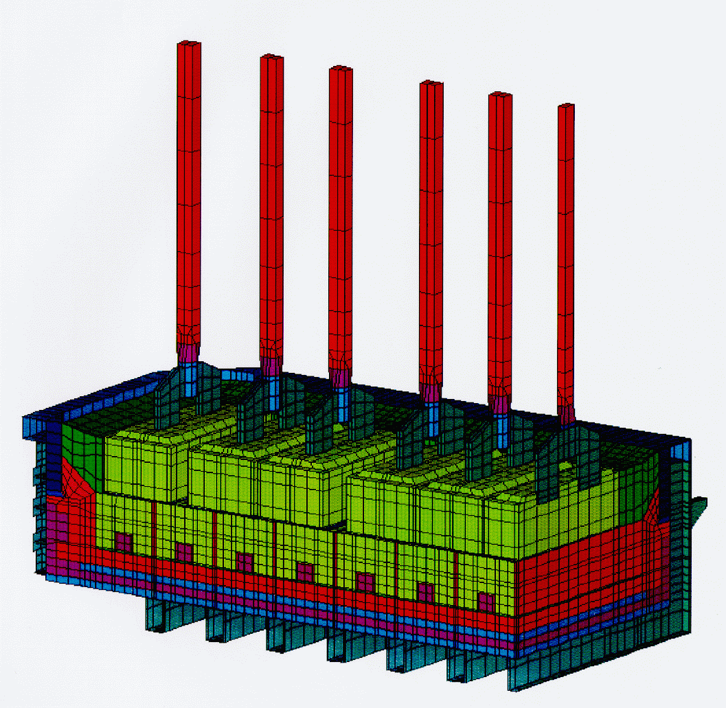
Early cathode failure during preheat and startup leads to significant costs due to relining and production loss. Figure 4 shows a quarter model of a cell used to perform a thermo-electric heat transfer analysis to predict the temperature profile during preheat. The same model is subsequently used to perform a thermal stress analysis to calculate the stresses in the cathode carbon [6]. The model was validated against field measurements and calibrated until acceptable results were produced. The stress analysis predicted cathode failure at the same locations observed in the field. Several design and operational alternatives were evaluated and a successful solution was found that drastically reduced the risk of early failure.

Figure 4: Coke preheat thermal stress model.


Magnetic Field Calculation

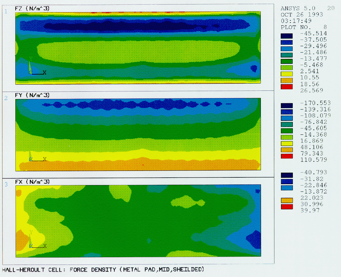
A model of a whole reduction cell with the surrounding busbar network and air was developed to calculate the distribution of the current density, magnetic field and resulting Lorenz forces in the metal pad [1]. The effects of magnetic shielding from the potshell were evaluated. Figure 5 show the force density distribution with and without shielding. This analysis was a first step towards the performance of a stability analysis of the cell.

Figure 5: : Force density distribution in the metal pad with and without sheilding from the potshell.

Conclusions

Finite element analysis is an important tool for the study of the behavior of aluminum reduction cells. FEA capabilities needed for effective use of the tool were outlined. The successful implementation of the technology for modeling four aspects of cell design was demonstrated.

The use of general purpose commercial FEA codes has several advantages over in-house programs. These codes can be customized to buffer the average user from the need to learn the various commands in these codes. Such customization frees the engineer to concentrate on the design process rather than on the modeling activity.

References

  1. "Thermo-Electro-Magnetic Modeling of a Hall-Héroult Cell", M. Dupuis and I. Tabsh, 1994 ANSYS Conference Proceedings, ed. D. E. Dietrich, M. C. Yaksh and D. F. Ostergaard (Pittsburgh, PA, Magnetics Symposium, pp. 9.3-9.13).

  2. "Thermo-Electric Analysis of Aluminum Reduction Cells" M. Dupuis and I. Tabsh, Proceedings of the 31 st Annual Conference of CIM, Light Metals Section, 1992, pp. 55-62.

  3. "Thermo-Electric Analysis of the Grande-Baie Aluminum Reduction Cell" M. Dupuis and I. Tabsh, Light Metals, ed. U. Mannweiler (Warrendale, PA: The Minerals, Metals & Materials Society, 1994, pp. 339-342).

  4. "Longitudinal Stress in Carbon Lining Blocks Due to Sodium Penetration", E. W. Dewing, Light Metals (Volume 3, 1974, pp. 879-887).

  5. "Shell Design Technique Considering the Sodium Swelling Phenomenon of Carbon Cathode Blocks" G. V. Asadi, M. Dupuis and I. Tabsh Light Metals Processing and Applications, ed. C. Bickert et al. (Montreal, QC, The Metallurgical Society of CIM, 1993, pp. 125-130).

  6. "Evaluation of Thermal Stresses due to Coke Preheat of a Hall-Héroult Cell" M. Dupuis and I. Tabsh, 1994 ANSYS Conference Proceedings, ed. D. E. Dietrich (Pittsburgh, PA, Volume 1, pp. 3.15-3.23).