Towards the Development of a 3D Full Cell and External Busbars Thermo-Electric Model
Marc Dupuis GéniSim Inc. 3111 Alger St., Jonquière, Québec, Canada G7S 2M9 email:
ABSTRACT
Taking advantage of the increasing power of computers, it is now practical to consider building a 3D full cell and external busbars thermo-electric model. In the present study, a 3D full cell quarter thermo-electric model and a 3D cathode half plus liquid zone and busbars thermo-electric model have been developed and solved using a PIII 800 MHz computer.
Developing a 3D full cell and external busbars thermo-electric model will constitute a step further towards the development of a fully "multi-physic" unified aluminium reduction cell model.
Already, a full cell thermo-electric model will be able to interact with a MHD model by providing it with accurate liquid zone current density and potshell temperature data and by receiving from it local liquid/ledge interface heat transfer coefficients.
INTRODUCTION
Technical justifications for the need to develop a fully "multi-physic" unified aluminium reduction cell model have been already discussed by the author in previous publications (1,2,3) and even more extensively very recently in (4). Furthermore, reference (4) provides the proposed steps leading towards the development of that fully "multi-physic" unified aluminium reduction cell model.
The first step in that proposed "research and development program" is the development of a 3D full cell and external busbars thermo-electric model. The present paper summarizes the work done trying to develop such a model using ANSYS® running on a PIII 800 MHz computer platform.
"COMPLETE" FULL CELL QUARTER THERMO-ELECTRIC MODEL
The starting point is the model presented last year in Figure 1 of reference (3). Rigorously, that model was not a "complete" full cell quarter thermo-electric model as only the cathode part of the model was made of thermo-electric elements. The anode part was rather made of electric only elements, with the thermal data coming from an anode panel thermo-electric model's solution. This explains why the anode crust was not part of the model.
This very convenient way of reducing the size of the model has been even more extensively used 10 years ago in the model presented in Figure 9 of reference (5). That model may have been the first 3D full cell and external busbars thermo-electric model, but only a very small fraction of that model was using thermo-electric elements. Reducing the model size this way to be able to fit it into a given computer in order to at least get a solution is useful. Unfortunately, as already explained in (4), by doing so, the problem solved is no longer a fully coupled thermo-electric one.
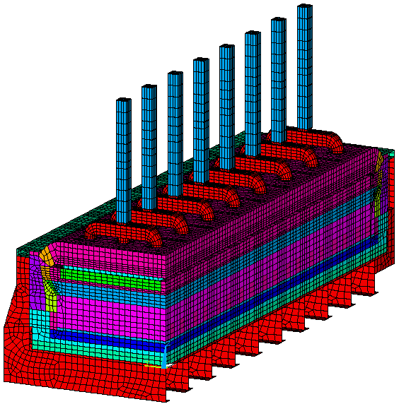
In Figure 1, the "complete" version of the 3D full cell quarter thermo-electric model is presented. That model is using 44,260 thermo-electric 3D elements to mesh the anode rods and studs, the anode carbon blocks, the cathodes blocks and the collector bars and flexibles. It is using 36,818 3D thermal only elements to mesh the anode crust, the ledge and the cathode lining, 8853 2D thermal only elements to mesh the cathode shell and 15165 3D electric only elements to mesh the liquid bath and metal.
The convergence of the ledge profile and hence the corresponding metal pad geometry is also part of the problem solution. A PIII 800 MHz computer with 384 MEG of RAM memory and equipped with a 20 GB SCSI hard disk took 52.48 CPU hours and 75.68 wall clock hours to compute the solution presented in Figures 2, 3 and 4.

Figure 1: "Complete" Full Cell Quarter Thermo-Electric Model Mesh
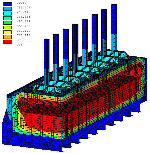
Figure 2: "Complete" Full Cell Quarter Thermo-Electric Model, Thermal Solution
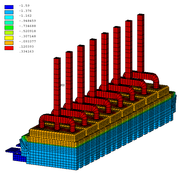
Figure 3: "Complete" Full Cell Quarter Thermo-Electric Model, Voltage Solution
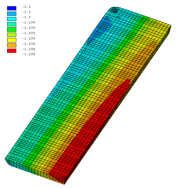
Figure 4: "Complete" Full Cell Quarter Thermo-Electric Model, voltage solution in metal
FULL CELL HALF THERMO-ELECTRIC MODEL
It is quite straightforward to mirror a full cell quarter model in order to produce a full cell half model (see Figure 5). Yet, there is no need to solve such a model unless asymmetric boundary conditions are applied on it. As the addition of the external busbar network will automatically introduce such an asymmetry between the positive and the negative side, adding the external busbar network to the model is the best thing to do at this point.
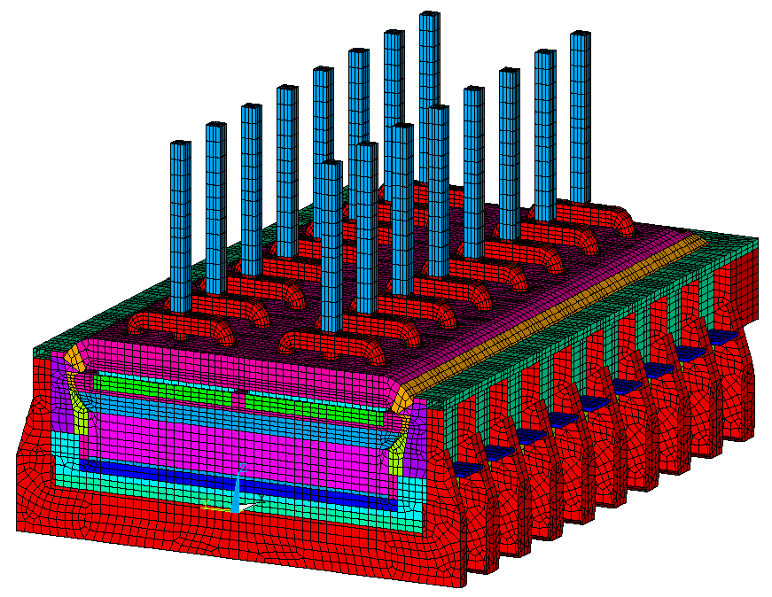
Figure 5: Full Cell Half Thermo-Electric Model Mesh
FULL CELL HALF AND EXTERNAL BUSBARS THERMO-ELECTRIC MODEL
Adding the external busbar network to a cell thermo-electric model doesn't add any new modeling challenges. In fact, this has already been done some time ago as in Figure 9 of reference (5). In the present demonstration model, the busbar network is much simpler and the anode beam has not been modeled (see Figure 6).
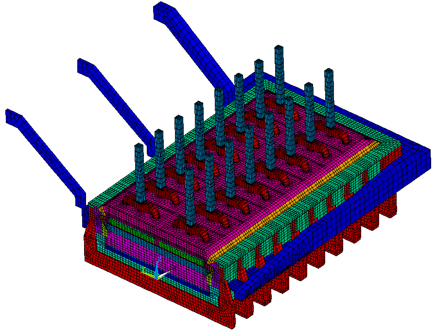
Figure 6: Full Cell Half and External Busbars Thermo-Electric Model Mesh
Unfortunately, it was clear that trying to solve that 211,648 elements full half cell and external busbars thermo-electric model on a PIII 800 MHz computer while the 105,096 elements full cell quarter thermo-electric model took 52.48 CPU hours and 75.68 wall clock hours to compute would require a lot of time, too much time!
CATHODE HALF PLUS LIQUID ZONE AND EXTERNAL BUSBARS THERMO-ELECTRIC MODEL
So again, the lack of computer power dictates that the size of the model should be cut back. Fortunately, it was demonstrated in (3) last year, that it is possible to compute quite accurately the current density in the liquid zone using only a cathode plus liquid zone model.
This time, in order to analyze the asymmetry generated by the external busbar network, a cathode half plus liquid zone and external busbars thermo-electric model will be solved (see mesh in Figure 7). That model made of 127,988 elements took 18.38 CPU hours and 22.25 wall clock hours to compute the solution presented in Figures 8 and 9.
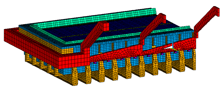
Figure 7: Cathode Half plus Liquid Zone and External Busbars Thermo-Electric Model Mesh
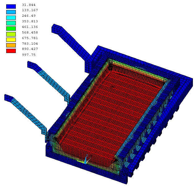
Figure 8: Cathode Half plus Liquid Zone and External Busbars Model, Temperature Solution
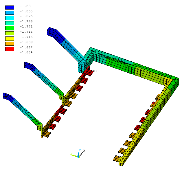
Figure 9: Cathode Half plus Liquid Zone and External Busbars Model, Busbar Voltage Solution
FULL CELL AND EXTERNAL BUSBARS THERMO-ELECTRIC MODEL
Obviously, if the goal is to couple a MHD model with a thermo-electric model, even a full half cell model is not enough as there is no such thing as a half cell MHD model. So, even if a full half cell and external busbars thermo-electric model is already to big to be solved in a reasonable CPU time on the current computer platform, the size of the model must be doubled again in order to get what is really needed, a 3D full cell and external busbars thermo-electric model that could be coupled with a MHD model.
Even if that ultimate thermo-electric model cannot be solved in a reasonable CPU time on a PIII 800 MHz computer, more recent computer like the P4 2.2 GHz no doubt could. While waiting for the next computer platform upgrade, there is no harm getting ready to use it right away by mirroring the full half cell model in order to generate the 423,296 elements full cell and external busbars model presented in Figure 10.
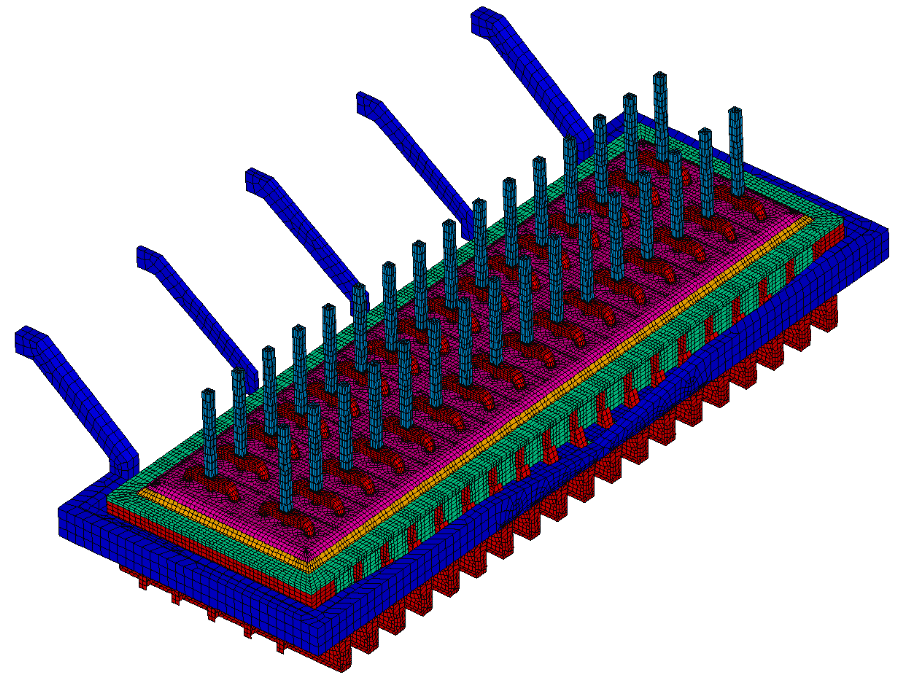
Figure 10: Full Cell and External Busbars Thermo-Electric Model Mesh
COUPLING FEATURES BETWEEN A MHD MODEL AND A THERMO-ELECTRIC MODEL
A MHD model, in order to be able to accurately compute the magnetic field and even to a greater extent the Lorentz force field in the liquid zone, must know, among other data, the accurate current density field in that liquid zone. And that liquid zone current density field cannot be accurately computed without knowing, among other data, the accurate ledge geometry as demonstrated in (3).
Similarly, a MHD model, in order to be able to accurately compute the magnetic field in the liquid zone, must know, among other data, the magnetization characteristics of the potshell. As the steel magnetization characteristics vary significantly with temperature, the accurate shielding characteristics of the potshell cannot be evaluated without knowing its temperature.
On the other hand, a thermo-electric model cannot accurately compute the ledge geometry without knowing, among other data, the local heat transfer coefficients of the liquid/ledge interface along the ledge perimeter. Those local heat transfer coefficients cannot be accurately computed without knowing the liquid zone velocity field computed by the MHD model.
RELATIONSHIP BETWEEN LOCAL HEAT TRANSFER COEFFICIENTS
OF THE LIQUID/LEDGE INTERFACE AND THE VELOCITY FIELD
In order to establish the last coupling described above, the relationship between the local heat transfer coefficients of the liquid/ledge interface and the liquid zone velocity field must be established.
Establishing this kind of boundary layer interface relationship is a "classic" chemical engineering problem. Very early, Dernedde (6) has proposed to use the following "classic" adimensional relationship in order to relate the local velocity to the local heat coefficient:

More recently, Nazeri (7) proposed the following direct relationship:

It is interesting to point out that equation (1) also predicts a very similar slope for velocity higher that 0.2 m/s as it can be seen in Figure 11.
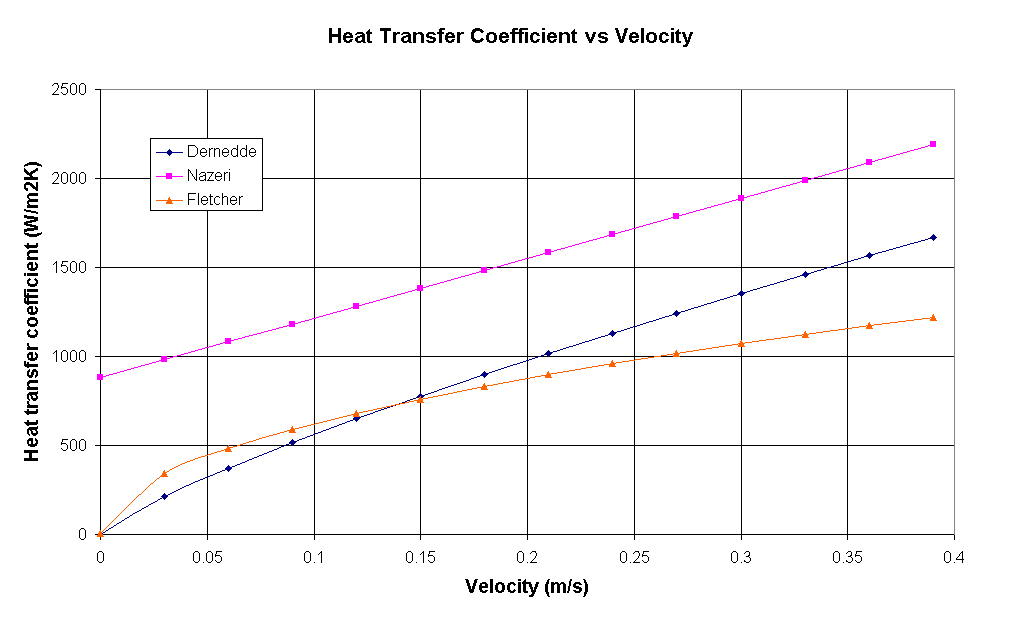
Figure 11: Relationship Between Heat Transfer Coefficient and Velocity
Finally, Fletcher (8) is proposing a somewhat different relationship:

This relationship predicts an average slope of 1850 (W/m2K)/(m/s) for velocity above 0.2 m/s which is about half of the value predicted by the first 2 equations.
Unfortunately, all those relationship predict on average heat transfer coefficients significantly lower than 2000 W/m2K, which is about the average value required in order to obtain the right heat flux through the ledge and side wall at the measured cell liquidus superheat. For that reason, the author thinks that a relationship like the one presented below should give better results in the model:

Of course, equation (4) is only an initial guess to be used on preliminary attempts to couple a MHD model to a thermo-electric model. Preliminary results will no doubt lead to a significant refinement of the proposed above relationship.
CATHODE HALF PLUS LIQUID ZONE AND EXTERNAL BUSBARS THERMO-ELECTRIC MODEL
USING LOCAL HEAT TRANSFER COEFFICIENTS
As the usage of a MHD model was not part of that study, in addition to the fact that the required solution of a full cell and external busbars thermo-electric model has not yet been generated, the proposed above coupling relationship has not been tested.
Nevertheless, the concept of using local heat transfer coefficients can be tested in the cathode half plus liquid zone and external busbars model. For the purpose of the test, the average heat transfer coefficients used respectively at the bath/ledge and metal/ledge interface were modulated using a cosine function. An amplitude of plus or minus 20%, compatible with equation (4) relationship was selected. The pattern of the modulation, presented in Figure (12), is compatible with a four recirculation loops pattern.
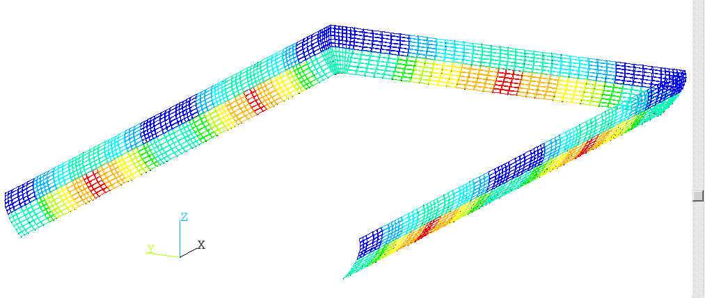
Figure 12: Local Heat Transfer Coefficients Modulation Pattern
Obviously, as a result, the converged ledge thickness varies significantly along the cell perimeter. The geometry and the voltage solution of the metal pad are also affected. Those results plus a subset of the obtained current density field are presented in Figures 13,14 and 15.
In the context of a MHD/thermo-electric model coupling convergence loop, that first thermo-electric model's solution would be fed to the MHD model that would then computes its initial velocity field solution that would then be used along with equation (4) relationship to reevaluate the local heat transfer coefficients. The alternative computation of the thermo-electric and MHD models until convergence would follow.
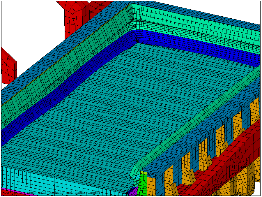
Figure 13: Converged Ledge Geometry Using Local Heat Transfer Coefficients
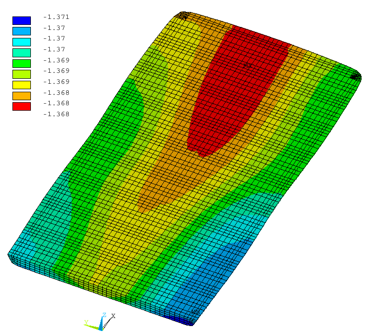
Figure 14: Voltage Solution in Metal Using Local Heat Transfer Coefficients
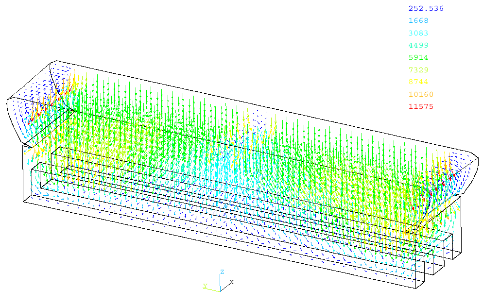
Figure 15: Current Density in the Section of the First Block from the Centerline
CONCLUSIONS
A 3D full cell quarter thermo-electric model and a 3D cathode half plus liquid zone and busbars thermo-electric model have been developed and solved using a PIII 800 MHz computer.
The 105,096 elements full cell quarter thermo-electric model took 52.48 CPU hours and 75.68 wall clock hours to compute including the convergence of the ledge profile and hence the corresponding metal pad geometry as part of the problem solution.
The 127,988 elements cathode half plus liquid zone and external busbars thermo-electric model took 18.38 CPU hours and 22.25 wall clock hours to compute including the convergence of the ledge profile and hence the corresponding metal pad geometry as part of the problem solution.
From the above results, it can be assessed that it will not be practical, maybe not even possible to solve on that PIII computer the 423,296 elements full cell and external busbars model that has also been developed. Yet, it is expected that a more recent and quite inexpensive computer like a P4 2.2 GHz computer could be successfully used for that purpose.
A tentative relationship between the local heat transfer coefficient at the liquid/ledge interface and the local liquids velocity has been proposed. The concept of using local heat transfer coefficients has been successfully test on a cathode half plus liquid zone and external busbars thermo-electric model.
REFERENCES